Method and device for treating liquids, using an electrolytic stage

a technology of electrolysis and liquid treatment, applied in the direction of water/sludge/sewage treatment, vapor condensation, cells, etc., can solve the problems of reducing the overall efficiency rating of the entire treatment method, reducing the absorption capability to an appreciable degree, etc., to achieve continuous system operation, reduce the loss of carrier gas, and reduce the overall energy consumption

Active Publication Date: 2010-07-29
NEUBERT SUSANNE
View PDF7 Cites 33 Cited by
  • Summary
  • Abstract
  • Description
  • Claims
  • Application Information

AI Technical Summary

Benefits of technology

[0034]In such a case, then the heat exchanger for the concentrate wastewater of the at least one preheat-separator is preferably chosen as a source of heat. An advantage of such an operation is that, the overall energy consumption is considerably reduced The reason for this, is that nearly all hot flows are put to use for heating colder flows. This is particularly true, if, at least one part of heat input for evaporation is carried to the wet carrier gas vapor mix in the at least one evaporation/condensation heat exchanger by means of the issuing, compressed and cleaned mix of carrier gas and dry vapor mix.
[0035]Especially advantageous is the provision, that the carrier gas is contained in a separate carrier gas circuit, in order to reduce the loss of carrier gas. In a closed circuit of this type, it is possible, because of the small loss of carrier gas, to employ even relatively expensive inert gases as the carrier gas. In their function as a means of transport for the waste liquids, considered in opposition to the use of air, the normal expectation is that these inert gases, contrary to air, cannot react with certain other components, especially with gaseous components. Further, for the retrieval of remaining gas in the separated condensate, an additional gas drying operation is carried out following the condensate collection tank. This extra drying operation is to dry the wet remaining gas from the condensate collection tank and return this saved gas, now in a desirable dry state, to the carrier gas circuit. In a much shortened carrying out of the method and its apparatus, the condensate entering the condensate separator is removed by a condensate exit-line with a check valve and sent to a condensate co...

Problems solved by technology

However, the quantity of water vapor still resident in this hot carrier gas can reduce to an appreciable degree a further abso...

Method used


Image

  • Method and device for treating liquids, using an electrolytic stage
  • Method and device for treating liquids, using an electrolytic stage
  • Method and device for treating liquids, using an electrolytic stage

Examples


Embodiment Construction

[0047]Referring now in more detail to the drawings, the invention will now be described in more detail.

[0048]Liquids for the invented treatment system, that is, suitable for feed-liquids to the system, include solutions at various dilution strengths, seawater, brackish back water, and the like, all of which are to be treated to become suitable drinking and service waters.

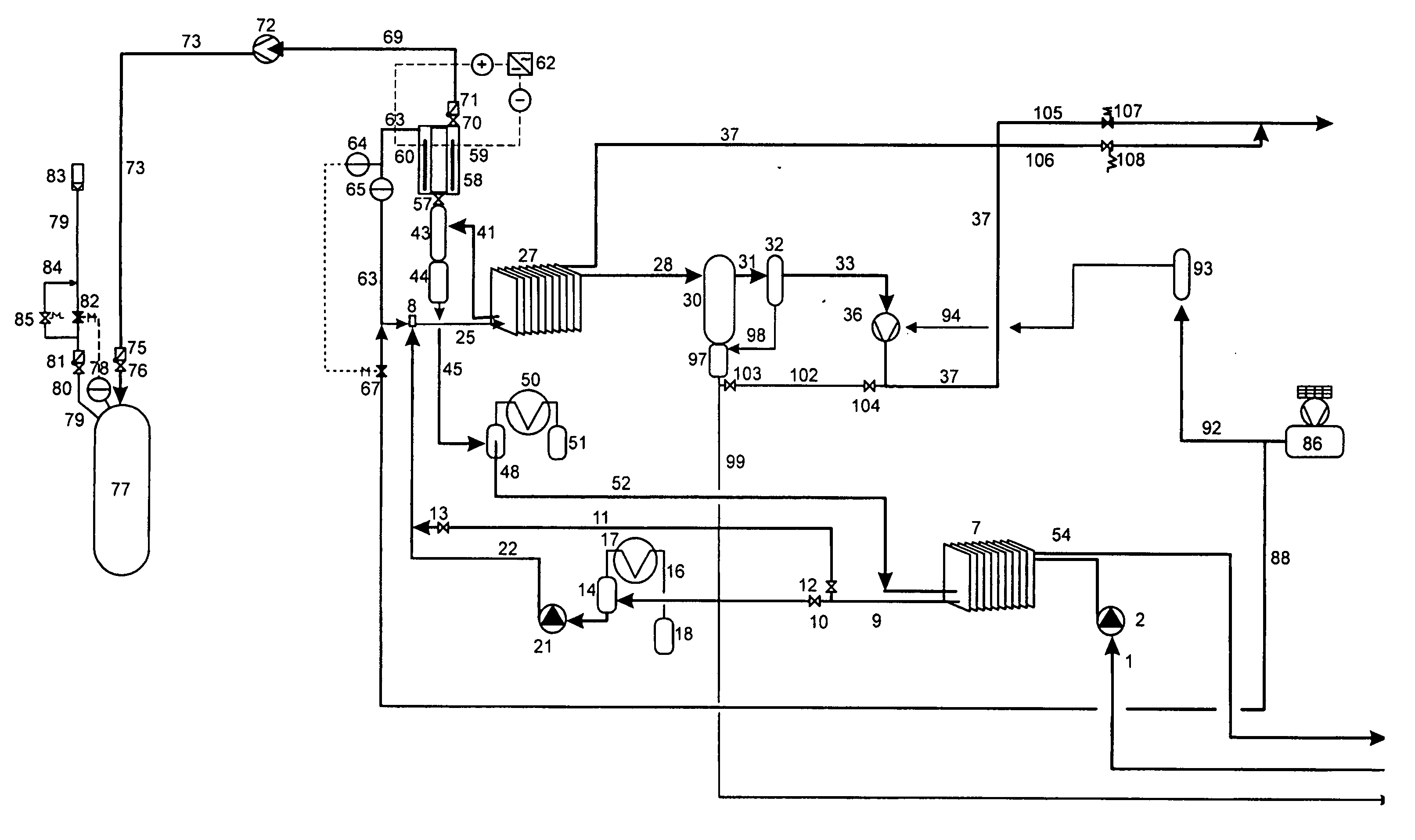
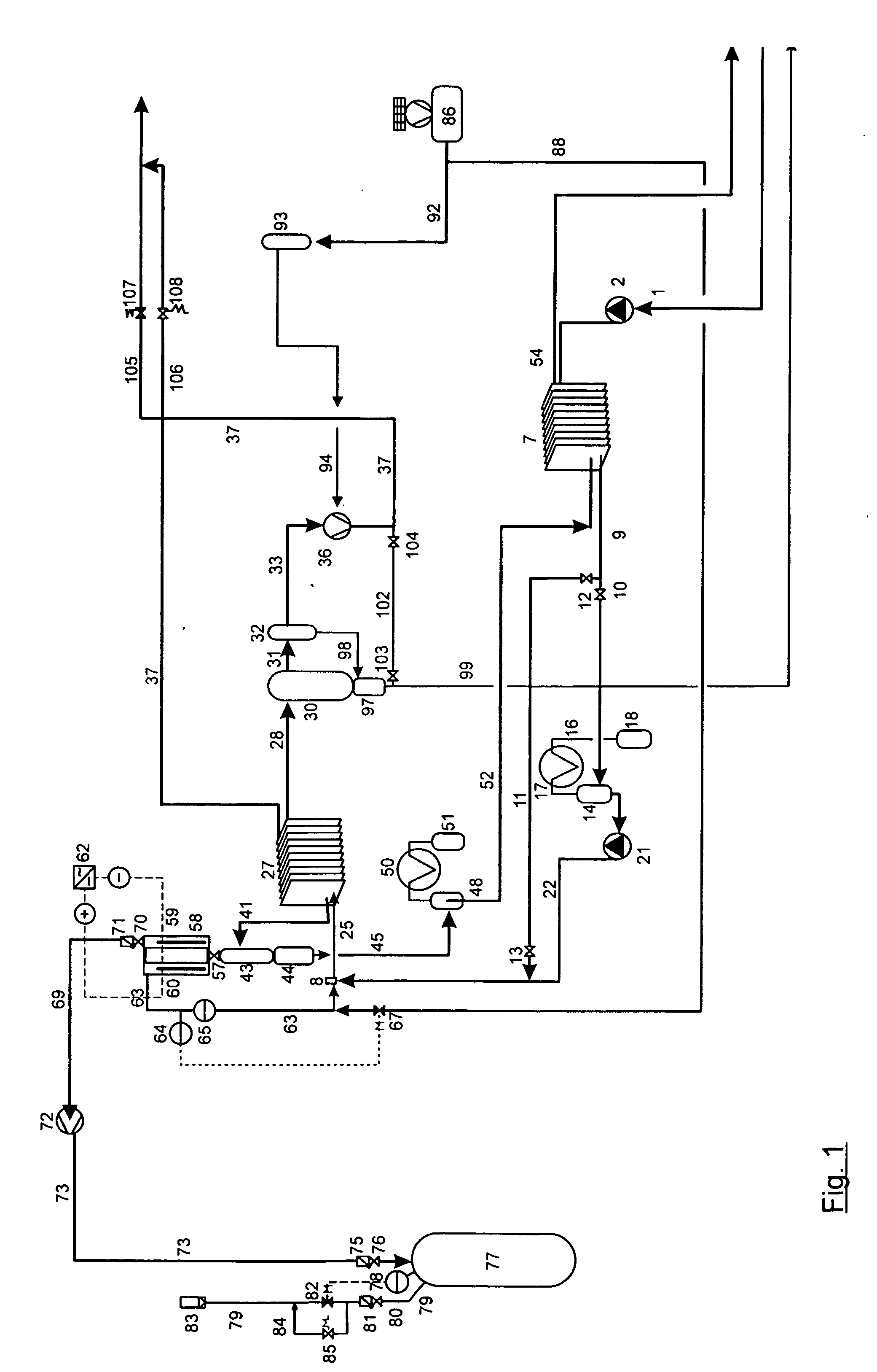
[0049]As can best be seen in the flow diagram of FIG. 1, feed-liquid entry is accomplished by feed inlet 1, wherein a pump 2 supplies the transport energy. The outlet of pump 1 is to an assembly for preheating and precleaning. This assembly comprises a preheat heat exchanger 7 and a separator 14 placed thereafter. Preheat heat exchanger 7 is, in this case, constructed as a condensate treatment liquid heat exchanger, which will be explained in detail later. In preheat heat exchanger 7 the temperature of the feed-liquid, which is dependent upon the thereby attendant pressure, is brought to a level which is as near as ...


PUM

PropertyMeasurementUnit
Temperatureaaaaaaaaaa
Pressureaaaaaaaaaa

Abstract

The invention relates to a method and device for treating liquids, particularly ocean, brackish water, refuse liquid, and waste water, wherein a hot carrier gas flow charged with water vapor is present in a predetermined treatment step as a hot water vapor carrier gas flow, particularly from a device for the treatment of liquids. According to the invention, at least a partial flow of the hot water vapor carrier gas flow is subjected to water vapor electrolysis in a water vapor electrolysis device in which at least part of the hydrogen and oxygen is separated from the hot water vapor carrier gas flow, and a dried carrier gas flow is created.

Description

CROSS-REFERENCE TO RELATED APPLICATION[0001]This application claims priority from International Application PCT / EP2008 / 002864, filed 11 Apr. 2008.BACKGROUND OF THE INVENTION[0002]The invention concerns a method and device for the treatment of liquids.[0003]The liquids include wastewater, which encompasses, for example, solutions at various dilution strengths, seawater, brackish back water and the like, with particular emphasis on the runoff of once potable and industrial service waters. These input liquids are, in the following, designated as “feed-liquid.” The generic EP 1 363 855 B1 discloses a method wherein the wastewater is subjected to evaporation by contact with a flow of high temperature carrier gas followed by condensation. The possibility exists, giving consideration to predetermined pressure and temperature of the carrier gas, that the carrier gas may bear and entrain water vapor in quantities which cannot be overlooked. The carrier gas, as air or an inert gas, enters the...

Claims


Application Information

Patent Timeline
IPC IPC(8): C02F1/461
CPCB01D1/22B01D1/2881B01D5/0039B01D5/0057B01D5/006C02F1/041Y02E60/366C02F1/448C02F1/461C02F2103/08C02F2201/46115C25B15/08C25B1/04C02F1/20Y02W10/33Y02W10/37Y02P20/133Y02A20/131Y02A20/124Y02E60/36
Inventor NEUBERT, JOACHIMSTAAB, KARL FERDINAND
Owner NEUBERT SUSANNE
Why Eureka
Try Eureka