Micro stage with 6 degrees of freedom

a micro stage and micro-stake technology, applied in the field of super-precise processing and sensing equipment, can solve the problems of various performance limitations, inability to meet the requirements of high velocity, high load and high dynamic performance of lithographic equipment, etc., and achieve low driven weight center, compact profile, and simple structure

Active Publication Date: 2010-07-29
TSINGHUA UNIV
View PDF4 Cites 16 Cited by
  • Summary
  • Abstract
  • Description
  • Claims
  • Application Information

AI Technical Summary

Benefits of technology

[0007]An object of the invention is to provide a 6 degree-of-freedom micro stage which can be used in a wafer table of a lithographic machine, which micro stage is able to compensate the positioning error of the wafer table of the lithographic machine and to achieve the leveling and focusing of the lithographic machine, and is applicable in super-precise processing and sensing fields for obtaining motions with 6 degrees of freedom. Meanwhile, the micro stage is expected to be featured as having a simple structure, a compact profile, a low driven weight center, low stator inertia, etc.
[0010]The micro stage of invention is benefited from adopting a parallel structure for achieving 6 degree-of-freedom motions and is advantageous over stacked structures by having a simple structure, a compact profile, a low driven weight center, low stator inertia, etc. Further, direct driving by electromagnetic force is used in the invention, as a result of which, there is no mechanical friction and damping, and high displacement resolution can be provided. The positioning error of the wafer table of the lithographic machine can be compensated and the leveling and focusing of the lithographic machine can be achieved. The micro stage, which operates on the basis of Lorentz Law, provides a linear relation between the output pushing force and the input electrical current, and thus the movement control technique for it can be well established.

Problems solved by technology

The former two types of micro stages, under the negative influence of non-linearity of frictional damping of their supporting systems and other factors, cannot meet the requirements of high velocity, high load and high dynamic performance of lithographic equipments.
Micro stages, driven by voice coil motors and supported by air-floating means, although meet the requirements of lithographic equipments, suffer from poor structural integrity, bulky stage body, high weight center, etc., which result in various limitations to their performances.

Method used


Image

  • Micro stage with 6 degrees of freedom
  • Micro stage with 6 degrees of freedom
  • Micro stage with 6 degrees of freedom

Examples


Embodiment Construction

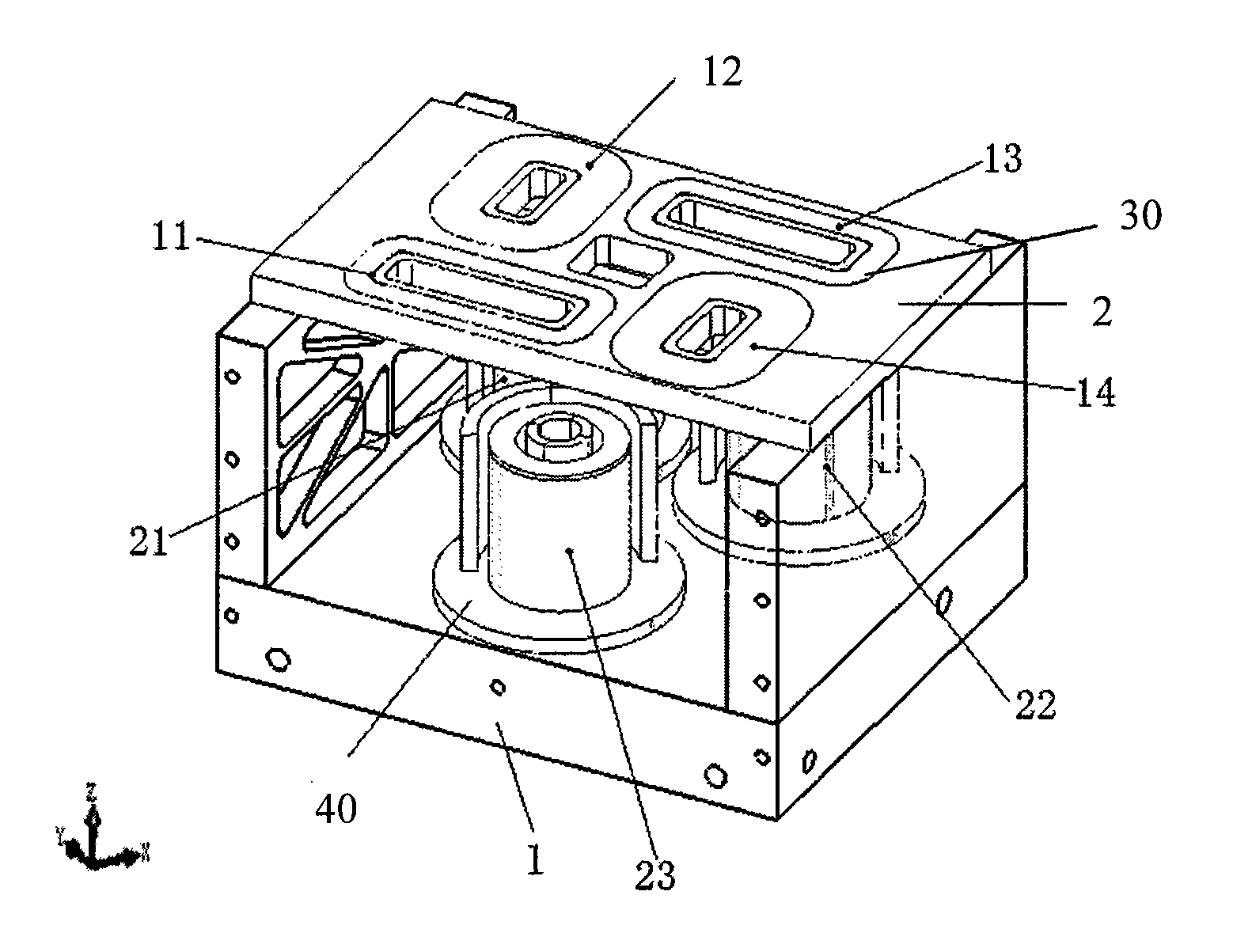
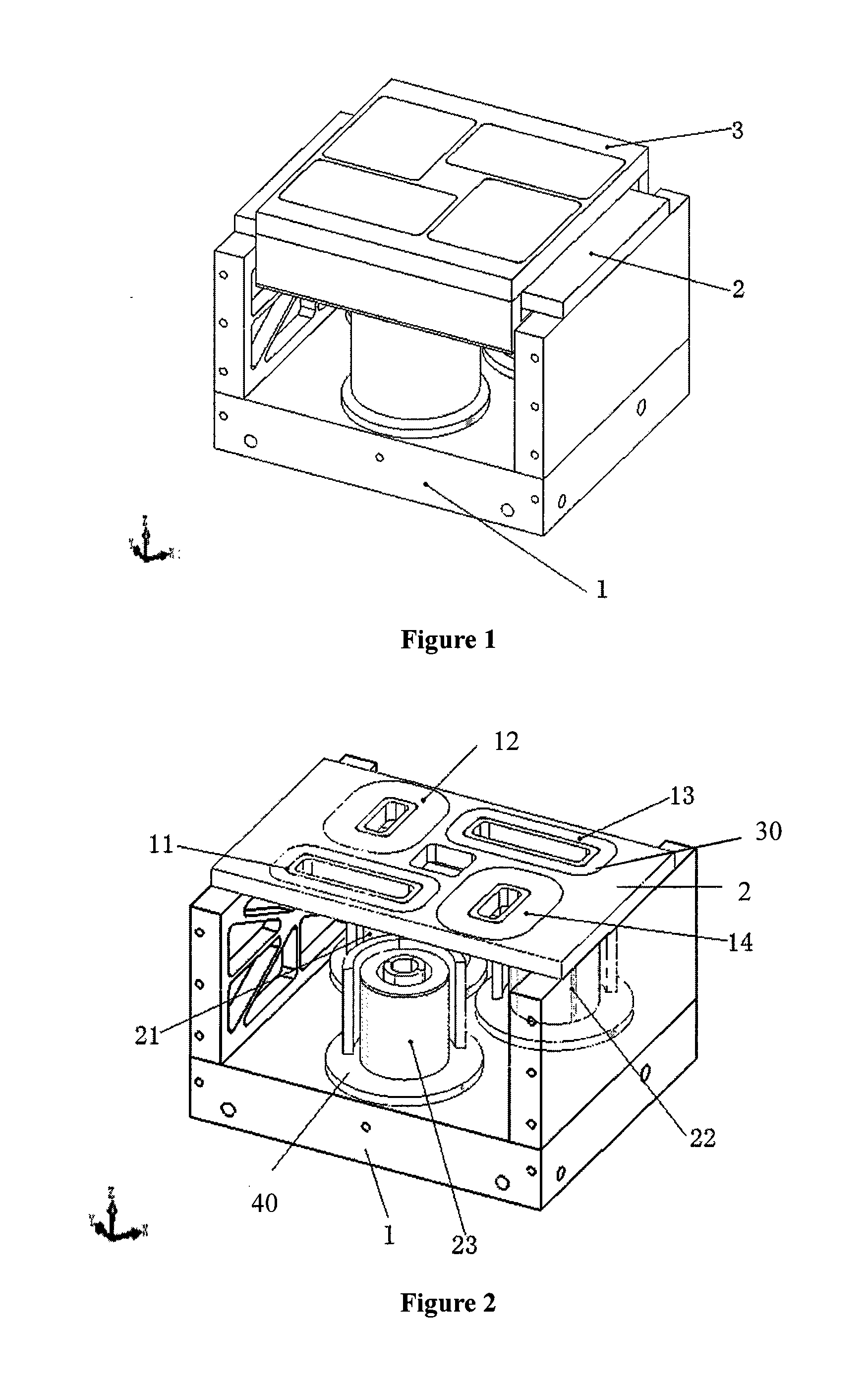
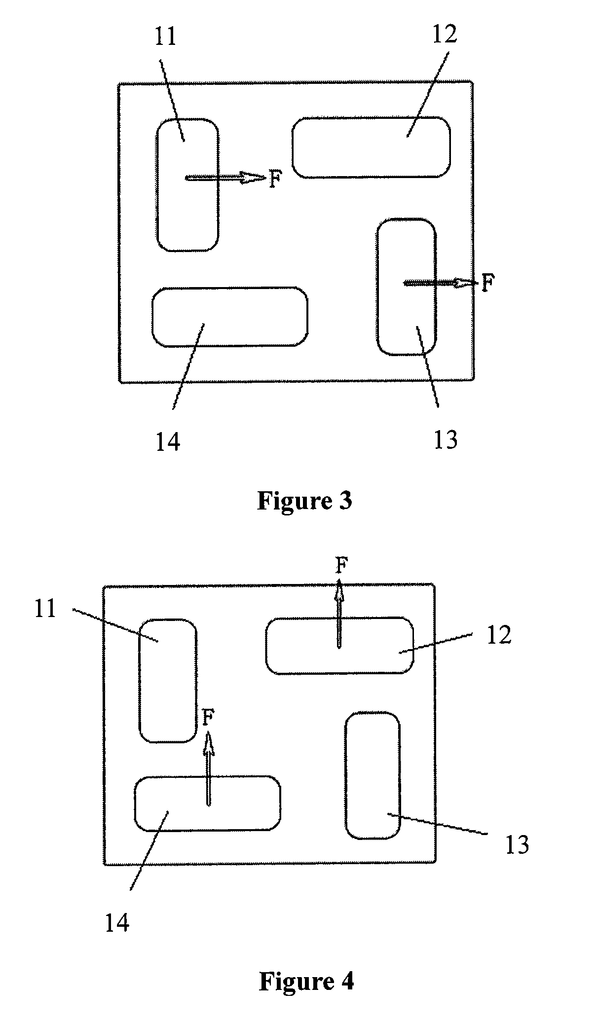
[0031]FIG. 1 is a perspective structural view of a 6 degree-of-freedom micro stage according to an embodiment of the invention. The micro stage comprises a micro stage base 1, a micro stage stator 2 and a micro stage mover 3. The micro stage has three sets of electromagnetic driving units arranged in a horizontal plane, wherein the driving axes of two of the three sets of driving units are parallel to each other but not coincided, and the driving axis of the third set of driving unit is orthogonal to the driving axes of the former two sets of driving units. The three sets of horizontally arranged driving units are configured to cooperatively obtain movements of the micro stage within the horizontal plane with 3 degrees of freedom in X, Y and θz directions. Each set comprises at least one electromagnetic driving unit, and each electromagnetic driving unit is composed of two parts, i.e., a planar permanent magnet polarized in a vertical direction and a coil, with the planar permanent ...


PUM


Abstract

A micro stage with 6 degrees of freedom used in super-precise processing and sensing equipment filed is disclosed. The micro stage has three sets of electromagnetic driving units arranged in a horizontal plane for driving the micro stage to obtain movements within the horizontal plane with 3 degrees of freedom in X, Y and θz directions and three electromagnetic driving units arranged in a vertical direction for driving the micro stage to obtain additional movements with 3 degrees of freedom in Z, θx and θy directions. Direct driving by electromagnetic force is used in the invention, resulting in advantages over stacked structures of having a simple structure, a compact profile, a low driven weight center, low stator inertia, etc. Thus, there is no mechanical friction and damping, and high displacement resolution can be provided. The positioning error of a wafer table of a lithographic machine can be compensated, and the leveling and focusing of the lithographic machine can be achieved. The invention is also applicable in super-precise processing and sensing fields for achieving 6 degree-of-freedom motions. The micro stage, which operates on the basis of Lorentz Law, provides a linear relation between the output pushing force and the input electrical current, and thus the movement control technique for it can be well established.

Description

TECHNICAL FIELD[0001]The invention relates to the super-precise processing and sensing equipment field and more particular to a micro stage, especially a micro stage with 6 degrees of freedom, which is mainly used in semiconductor lithographic equipment.BACKGROUND ART[0002]Micro stages having high precision and rapid responding ability are of great importance in modern manufacture technology and reflect the high-tech level of technical development of a country. In a super-precise machine tool, a super-precise micro stage is used for compensating the error of a feeding system, for achieving super-precise processing. In large scale integrated circuit manufacturing, super-precise micro stages are used in lithographic equipments for achieving micro positioning and micro feeding. In scanning microscopes, super-precise micro stages are used for detecting sample surface profile and nano processing. In biotechnology, super-precise micro stages are used in cell treatments, for achieving indu...

Claims


Application Information

Patent Timeline
Patent Type & Authority Applications(United States)
IPC IPC(8): H02K41/035
CPCG03F7/70758G03F7/70725
Inventor ZHU, YUWANG, JINSONGZHANG, MINGLI, GUANGXU, DENGFENGYIN, WENSHENGDUAN, GUANGHONGYANG, KAIMING
Owner TSINGHUA UNIV
Why Eureka
Try Eureka