
Method for forming multilayer structure, method for manufacturing display panel, and display panel

a multi-layer structure and manufacturing method technology, applied in the direction of instruments, semiconductor devices, optics, etc., can solve problems such as connection errors between the third conductive layer, and achieve the effect of fast etching

Active Publication Date: 2010-07-29
ORTUS TECH
View PDF8 Cites 8 Cited by
  • Summary
  • Abstract
  • Description
  • Claims
  • Application Information

AI Technical Summary

Benefits of technology

[0012]Objects of the present invention are to provide an improved method for forming a multiplayer structure and an improved method for manufacturing a display panel, and to provide an improved display panel.
[0019]In another aspect, the present invention provides a method of forming a multilayer structure, including forming a first layer, a surface of the first layer being exposed to a condition that makes said surface subject to faster etching than other portion of the first layer for a prescribed etching method; forming a second layer on said surface of the first layer; forming a third layer on the second layer; and forming a hole penetrating through the first, second and third layers using said prescribed etching method, wherein the third layer is configured such that in the step of forming the hole, a reverse tapered shape at an edge of the second layer due to said surface of the first layer is substantially prevented.

Problems solved by technology

This results in connection error between the third conductive layer 66 and the first conductive layer 65.

Method used


Image

  • Method for forming multilayer structure, method for manufacturing display panel, and display panel
  • Method for forming multilayer structure, method for manufacturing display panel, and display panel
  • Method for forming multilayer structure, method for manufacturing display panel, and display panel

Examples


Embodiment Construction

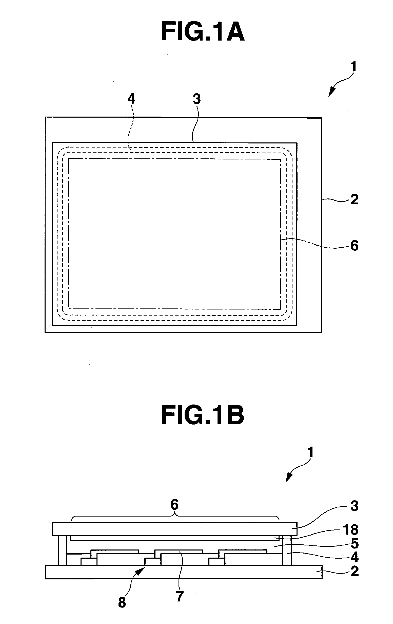
[0044]Exemplary embodiments for implementing the present invention will now be described with reference to the figures. As shown in FIGS. 1A and 1B, an active matrix type liquid crystal display panel 1 is provided with a first substrate 2 and a second substrate 3 that are arranged to face each other. The first substrate 2 and the second substrate 3 are bonded with a seal material 4 that is formed in a frame shape. Between the first substrate 2 and the second substrate 3, a liquid crystal layer 5 is formed by disposing liquid crystal in a region surrounded by the seal material 4. The liquid crystal display panel 1 is provided with a plurality of pixels that is arranged in a matrix in a display area 6.

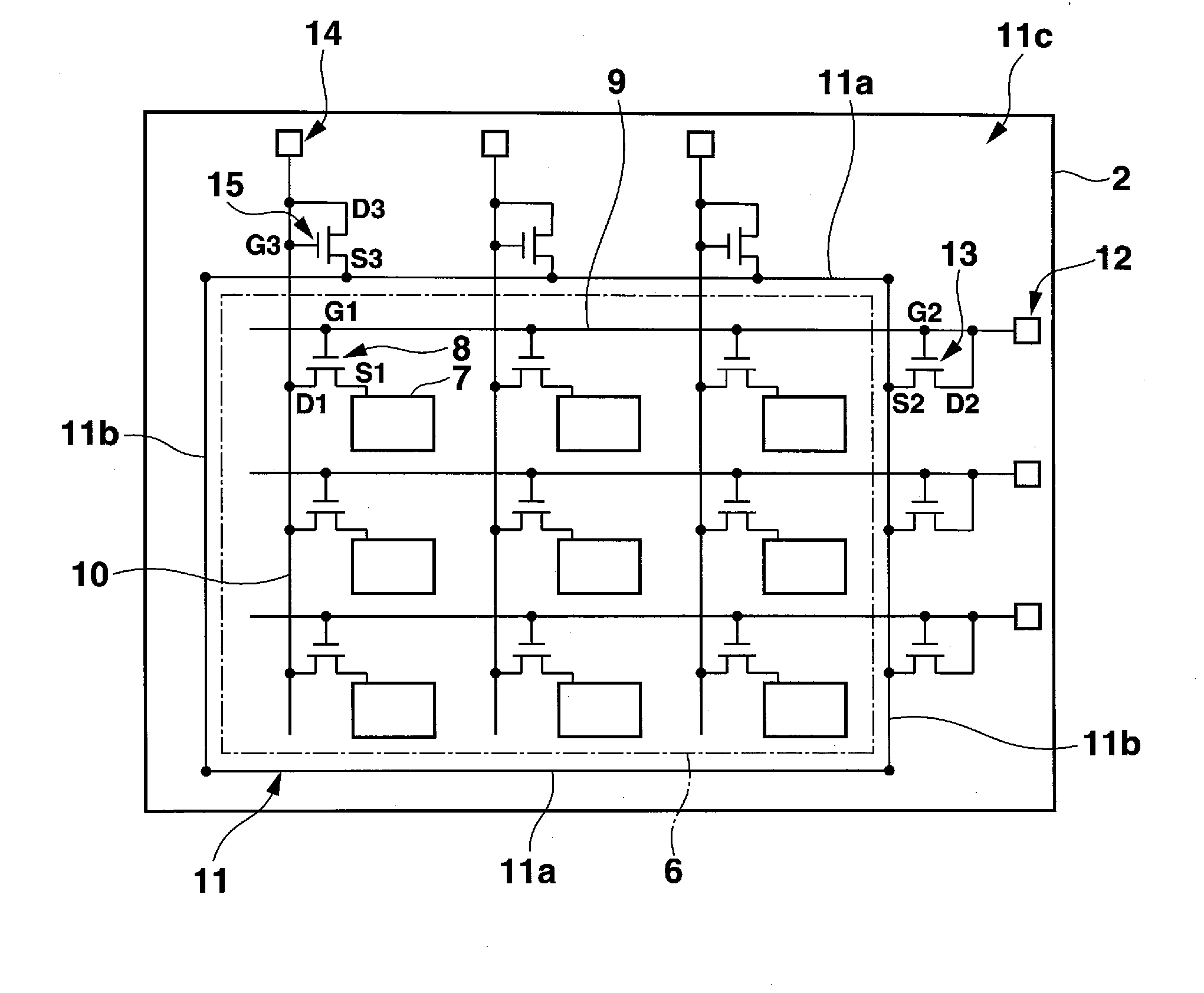
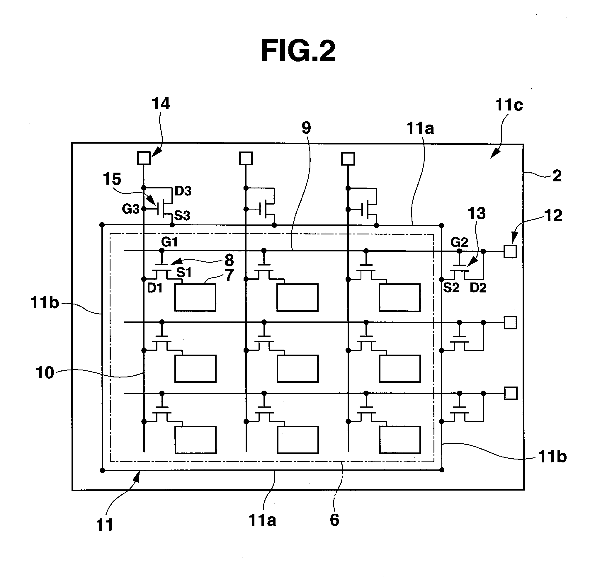
[0045]FIG. 2 is a plan view of an equivalent circuit diagram of a thin film transistor array that is formed on the first substrate 2. The first substrate 2 is provided with a plurality of pixel electrodes 7 that is arranged in a matrix in the display area 6 so as to associate one pixel w...


PUM

PropertyMeasurementUnit
flow rateaaaaaaaaaa
flow rateaaaaaaaaaa
flow rateaaaaaaaaaa

Abstract

A method for forming a multilayer includes a process for forming a first conductive layer on a substrate; a process for forming a first insulating layer on the first conductive layer; a process for forming a second conductive layer on the first insulating layer and patterning the deposited second conductive layer; a process for forming a second insulating layer over the substrate so as to cover the patterned the second conductive layer; a process for forming a third insulating layer on the second insulating layer, wherein an etching speed of the third insulating layer is faster than that of the second insulating layer; and a process for forming contact holes at once that expose at least a part of the first conductive layer to the first insulating layer, the second insulating layer and the third insulating layer.

Description

CROSS-REFERENCE TO RELATED APPLICATIONS[0001]This application is based upon and claims the benefit of priority from Japanese Patent Application No. 2009-015154, filed in Japan on Jan. 27, 2009, and Japanese Patent Application No. 2009-286291, filed in Japan on Dec. 17, 2009, both of which are hereby incorporated by reference in their entireties.BACKGROUND OF THE INVENTION[0002]1. Field of the Invention[0003]The present invention relates to a method for forming a multilayer structure, a method for manufacturing a display panel, and a display panel.[0004]2. Description of the Related Art[0005]In recent years, active matrix type liquid crystal display panels that employ a thin film transistor (TFT) as a switching element have been developed. On the display area of the active matrix type liquid crystal display panel, there are provided a plurality of pixels arranged in a matrix. That is, on one of two substrates arranged to face each other, a plurality of pixel electrodes are arranged i...

Claims


Application Information

Patent Timeline
Patent Type & Authority Applications(United States)
IPC IPC(8): G02F1/136H01L33/00H01L21/336H01L21/768
CPCG02F1/13454H01L27/1248H01L27/124G02F1/136204
Inventor TANAKA, YOSHITAKACHIKAMORI, HIROYUKI
Owner ORTUS TECH
Learn More