Pulse modulation method and optical fiber laser

a pulse modulation and optical fiber technology, applied in the direction of laser details, active medium shape and construction, electrical equipment, etc., can solve the problems of sbs attaining a greater gain or being more likely to occur, and achieve the effect of increasing the signal width, enhancing the pulse energy, and increasing the modulated voltag

Inactive Publication Date: 2010-07-29
MEGAOPTO
View PDF4 Cites 6 Cited by
  • Summary
  • Abstract
  • Description
  • Claims
  • Application Information

AI Technical Summary

Benefits of technology

[0009]In a laser scheme which pulses output light by directly modulating a seed light source such as an LD (Laser Diode) which outputs seed light, increasing the signal width (the width of a driving signal pulse for optical pulse generation, which is the time width of a modulated voltage defining the driving time of the LD) of a modulated voltage applied to the seed light source in order to enhance the pulse energy raises the probability of SBS occurring in the process of amplifying the power of seed light and thereby destroying optical components constructing the optical fiber laser and the pumping light source.
[0010]That is, when attention is focused on the half width of the output light spectrum from the LD acting as the seed light source, increasing the signal width of the modulated voltage for pulsing the seed light for obtaining a sufficient optical pulse energy narrows the half width of the spectrum. The SBS increases its gain as the spectrum width is narrower, thus leaving a problem that, when the modulated voltage applied to the seed light source has a longer pulse signal width, the SBS attains a greater gain or is more likely to occur.
[0011]The present invention has been developed to eliminate the problems described above. It is an object of the present invention to provide a pulse modulation method and optical fiber laser having a structure for effectively suppressing nonlinear optical phenomena such as SBS which increase as an optical pulse becomes wider when amplifying the optical pulse with a predetermined period as seed light.

Problems solved by technology

The SBS increases its gain as the spectrum width is narrower, thus leaving a problem that, when the modulated voltage applied to the seed light source has a longer pulse signal width, the SBS attains a greater gain or is more likely to occur.

Method used


Image

  • Pulse modulation method and optical fiber laser
  • Pulse modulation method and optical fiber laser
  • Pulse modulation method and optical fiber laser

Examples


first embodiment

of Pulse Modulation Method

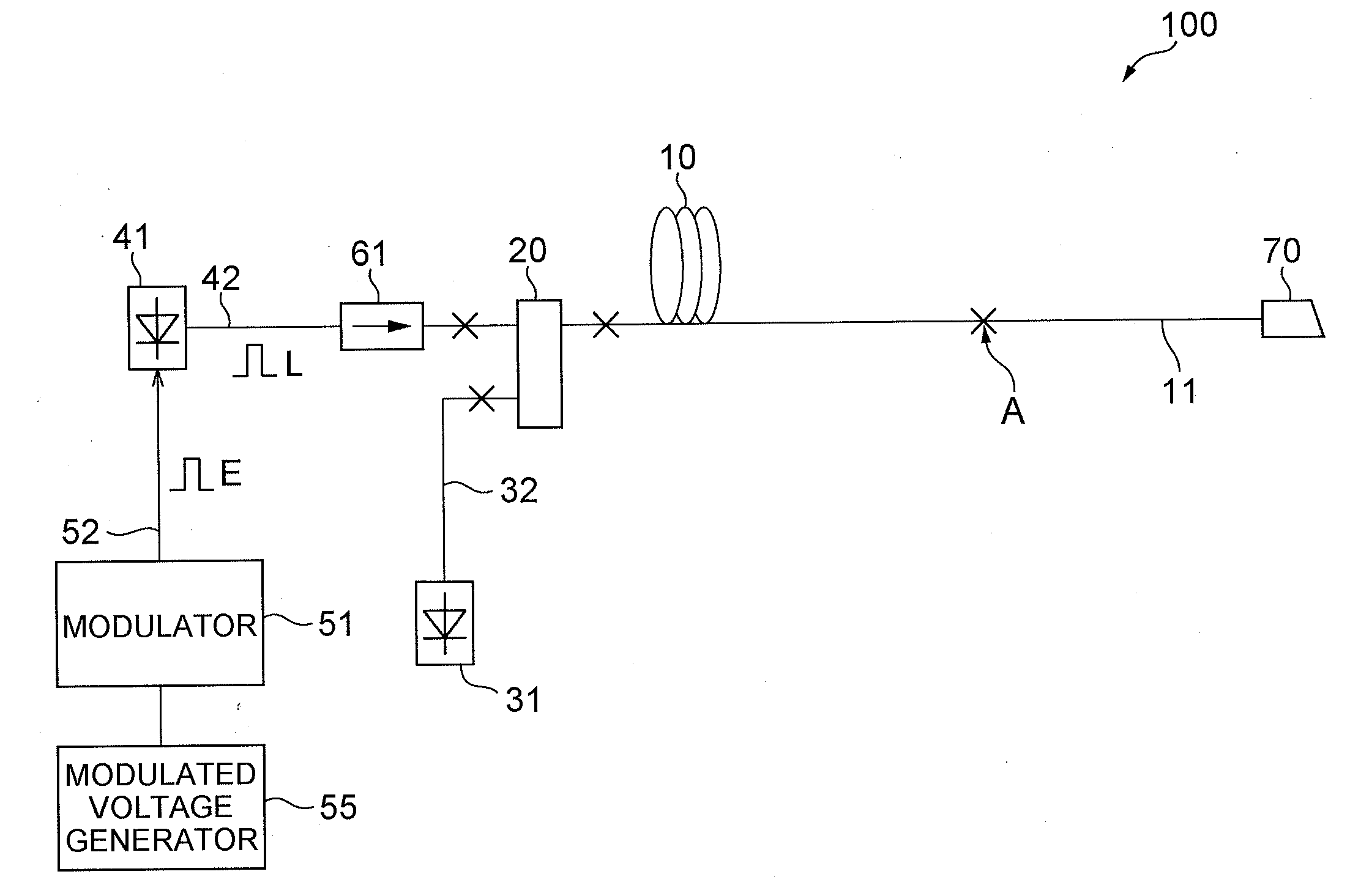
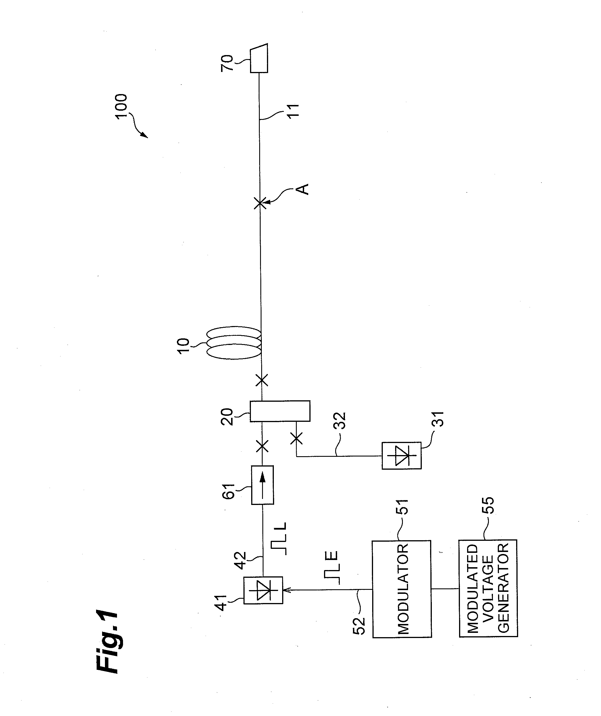
[0056]The first embodiment of the pulse modulation method according to the present invention will now be explained. In the following, operations in the case where the pulse modulation method is applied to the optical fiber laser 100 shown in FIG. 1 will be explained. Hence, this pulse modulation method is achieved when the modulator 51 directly modulates the seed light source 41. FIG. 8 is a chart for explaining the first embodiment of the pulse modulation method according to the present invention. That is, the modulated voltage E applied from the modulator 51 to the seed light source 41 is adjusted according to the modulation pattern shown in FIG. 8. A modulation period in the modulation pattern of the modulated voltage E corresponds to one cycle of an optical pulse to be produced and is constituted by a signal ON period T1 and a signal OFF period T2. In the signal ON period T in the pulse modulation method according to the first embodiment, a modulated vo...

second embodiment

of Optical Fiber Laser

[0072]FIG. 16 is a diagram showing the structure of the second embodiment of the optical fiber laser according to the present invention. In FIG. 16, the optical fiber laser 200 according to the second embodiment has the same structure as that of the optical fiber laser 100 according to the first embodiment in that it comprises an amplification optical fiber 10, an optical coupler 20, a pumping light source 31, an optical fiber 32, a seed light source 41, an optical fiber 42, a modulated voltage generator 55, an electric signal line 52, an optical isolator 61, a transmission optical fiber 11, and a light exit end 70. However, while the optical fiber laser 100 according to the first embodiment has a direct modulation type structure in which the modulator 51 modulates the seed light source 41, the optical fiber laser 200 according to the second embodiment has an external modulation type structure. Specifically, the optical fiber laser 200 according to the second e...

third embodiment

of Optical Fiber Laser

[0074]FIG. 17 is a diagram showing the structure of the third embodiment of the optical fiber laser according to the present invention. The optical fiber laser 300 according to the third embodiment is the same as the first embodiment in terms of the structure in which the modulator 51 directly modulates the seed light source 41, but differs therefrom in terms of the pumping method. That is, the optical fiber laser 300 according to the third embodiment and the optical fiber laser 100 according to the first embodiment structurally differ from each other in that they have structures for performing backward pumping and forward pumping, respectively.

[0075]In particular, the optical fiber laser 300 shown in FIG. 17 comprises an amplification optical fiber 10, an optical divider 21, a pumping light source 33, an optical fiber 34, a seed light source 41, an optical fiber 42, a modulator 51, a modulated voltage generator 55, an electric signal line 52, an optical isolat...


PUM


Abstract

The present invention relates to a pulse modulation method and the like having a structure for effectively suppressing nonlinear optical phenomena which increase as an optical pulse becomes wider when amplifying the optical pulse with a predetermined period as seed light. A modulator performs pulse modulation for a laser light source which is a seed light source or light outputted from the laser light source. A modulation pattern of a modulated voltage outputted from the modulator is adjusted such as to include a plurality of pulse components each having a signal width shorter than the pulse width of the optical pulse as an optical pulse generation pattern within a modulation period corresponding to a period of the optical pulse.

Description

CROSS-REFERENCE TO RELATED APPLICATION[0001]This application claims priority to Provisional Application No. 61 / 146,846 filed on Jan. 23, 2009 by the same Applicant, which is hereby incorporated by reference in its entirety.BACKGROUND OF THE INVENTION[0002]1. Field of the Invention[0003]The present invention relates to a pulse modulation scheme which repeatedly generates optical pulses of a predetermined period as seed light for obtaining high-power output light, and an optical fiber laser to which such a scheme is applied.[0004]2. Related Background of the Invention[0005]Attention has currently been paid to processing techniques using laser light, so that demands for high-power laser light sources have been increasing in the fields of processing, medical care, and the like. Among various laser light sources, those attracting attention in particular are optical fiber lasers. Such an optical fiber laser employs an amplification optical fiber, whose core is doped with a rare-earth elem...

Claims


Application Information

Patent Timeline
Patent Type & Authority Applications(United States)
IPC IPC(8): H01S3/067H01S3/10
CPCH01S3/067H01S3/06708H01S3/094011H01S2301/03H01S3/10092H01S3/1618H01S3/09408
Inventor TAMAOKI, SHINOBU
Owner MEGAOPTO
Why Eureka
Try Eureka