[0011]The present invention is directed to a Raman shifter with improved optical efficiency and robustness, particularly for high power applications. The invention implements a folded path within a Raman cell substantially without beam overlap, thereby improving optical efficiency and avoiding potential problems related to multi-pass illumination of a medium portion. In addition, a folded path can be implemented in accordance with the invention free from coated
optics for beam redirection, thereby allowing for improved optical efficiency,
reduced susceptibility to damage, and improved operating bandwidth. The invention also allows for improved medium circulation for multi-pass Raman cell implementations. Additionally, the invention provides for improved transmission of a beam through an entry and / or exit window of a cell containing a shifting medium.
[0014]The source beam may be of any suitable type and may be operated according to operating parameters desired for the specific application under consideration. However, the invention has particular advantages for high power applications where it may be desired to avoid
optical breakdown or damage to the medium by a high power (e.g., condensed
diameter, high
pulse energy and high
pulse repetition frequency) beam. For many applications, the cell will contain a pressurized gas, where the gas is selected together with the source wavelength to provide the desired output beam wavelength. The decreased
optical density and increased
gain length with a non-overlapping path geometry has advantages for any implementation. Additional advantages are realized in the case of gases such as
methane that are susceptible to sooting due to optical degradation, particularly in high power applications.
[0017]In accordance with another aspect of the present invention, a Raman shifter is adapted for use across a wide
wavelength band. Specifically, the shifter includes a port for admitting, into an interior of a cell, a source beam of
radiation having a first nominal wavelength, and optics to redirect the
optical beam for a plurality of passes across a wavelength shifting region of the cell where the redirecting optics is operative to redirect beams with an optical efficiency of at least 95% across a
wavelength band having a bandwidth of at least 1000 nm. As noted above, folded path configurations in Raman shifters have, heretofore, generally been implemented using coated optics. Among other disadvantages, such coated optics generally have highly wavelength dependent performance characteristics. A Raman shifter in accordance with the current aspect of the present invention has a high optical efficiency over a band of at least 1000 nm and, preferably, across a
wavelength band extending across the
visible spectrum and, more preferably, from within the
ultraviolet spectrum portion of the spectrum into the
infrared portion of the spectrum. This can be readily achieved, for example, by using an internal reflectance element such as a
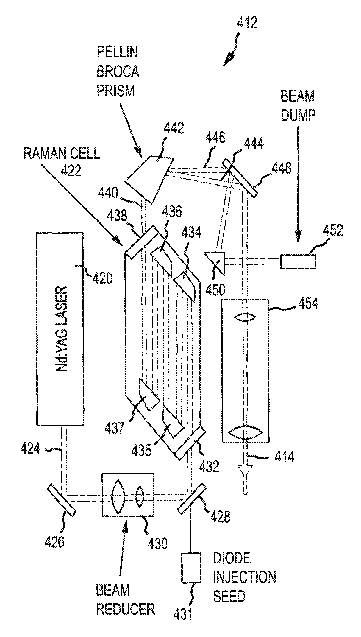
prism for beam redirection. A related process involves providing a Raman cell having folding optics, first using the folding optics to redirect a beam having a first nominal wavelength, and second using the folding optics to redirect a beam having a second nominal wavelength, where the second nominal wavelength differs from the first nominal wavelength by at least 1000 nm.
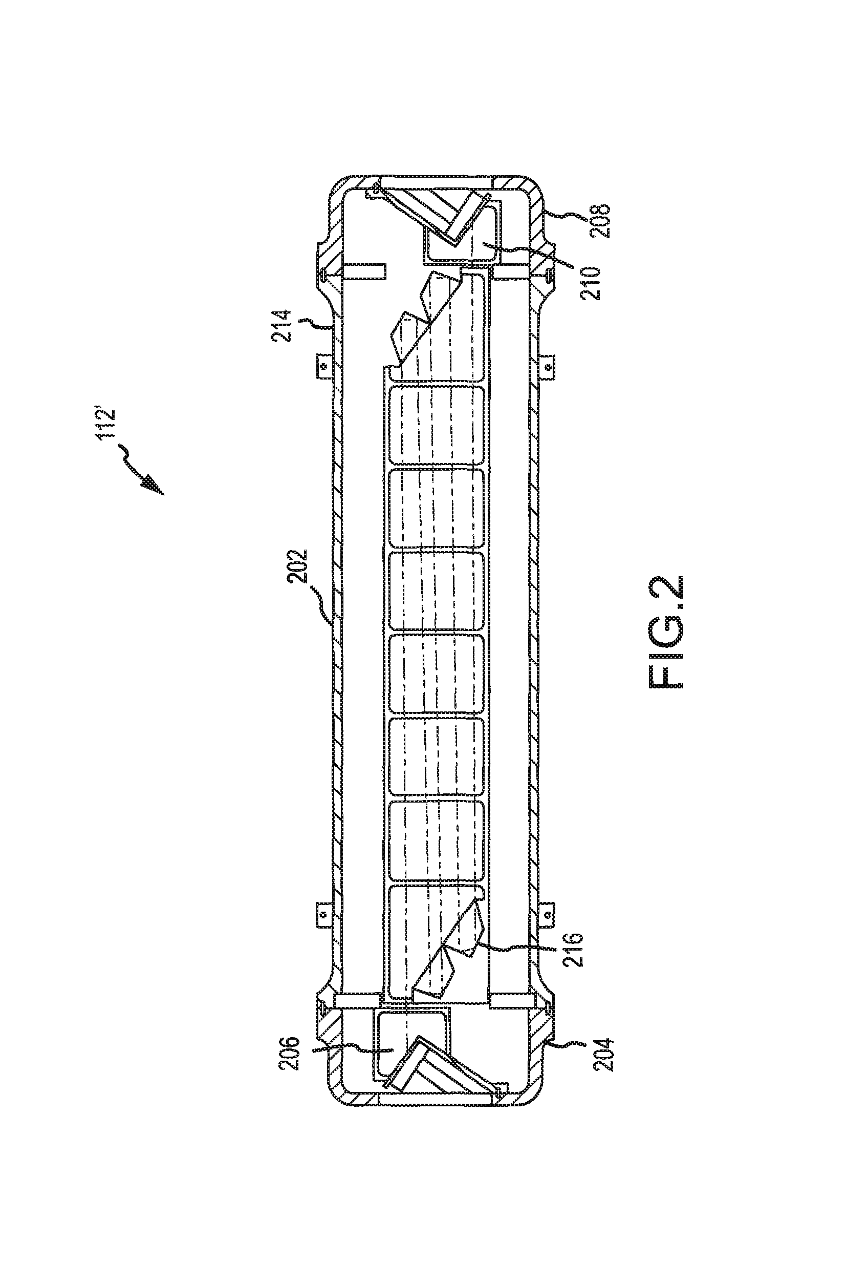
[0019]According to a still further aspect of the present invention, a multi-pass Raman shifter is provided with improved medium circulation. As discussed above, it is desirable, particularly for high power applications, to circulate the shifting medium so as to reduce or substantially avoid multiple illuminations of the same portion of the medium during a short
time frame. Such circulation is particularly problematic for folded path or multi-pass Raman cell geometries. A Raman shifter constructed in accordance with the present aspect of the invention includes a cell containing the
stimulated Raman scattering medium, optics for defining a folded path through the cell for a laser beam where the folded
optical path includes a first path section and a second path section contained substantially within a single plane, and a circulation
system for circulating the medium such that the medium flows transverse to a first axis of the first path section at the location of the first path section and transverse to a second axis of the second path section at a location of the second path section. In one implementation, the various sections of a folded path are contained within a single plane and structure is provided for circulating the medium substantially perpendicular to the path sections. In this regard, the circulation
system may flow the gas in the plane of the path sections or, more preferably, substantially perpendicular to the plane. The flow rate may be selected in relation to the beam width and the
pulse repetition frequency such that multiple successive pulses do not illuminate a particular portion of the medium (i.e., a given portion of the medium is illuminated by no more than a predetermined number—one or more—of pulses). In this manner, reduced optical performance associated with multiple illuminations is reduced or substantially eliminated. A corresponding process in accordance with the present invention involves transmitting a beam through a Raman cell along a folded path including first and second sections that are included in a common plane, and circulating the medium in a direction transverse to the path sections and, preferably, transverse to the common plane.
[0020]In accordance with a still further aspect of the present invention, a Raman cell with improved
transmission properties is provided. The Raman cell generally includes a cell body for containing the shifting medium, an entry window for allowing transmission of a source beam into the cell, and an exit window for allowing transmission of the shifted beam from the cell. In accordance with the present aspect of the invention, at least one of the entry and exit windows is disposed at a Brewster angle relative to the propagation axis of the associated beam for improved transmission. A corresponding method involves providing a Raman cell including a window for transmission of a beam therethrough and transmitting a beam through the window, wherein the beam is disposed at a Brewster angle relative to a surface of the window.
[0021]In accordance with another aspect of the present invention, beam forming optics are used to optimize the performance of a Raman cell. As discussed above, particularly for high power applications employing
methane as a shifting medium, significant sooting can occur if a tightly focused beam is employed in the Raman cell. However, it is desirable to employ a beam having a
high energy density. It has been found that
improved performance can be achieved, in this regard, by forming the beam such that the beam is free from any beam
waist within the cell, and has an
energy density that is greater, even if only slightly, at the exit window of the cell than at the entrance window. A corresponding
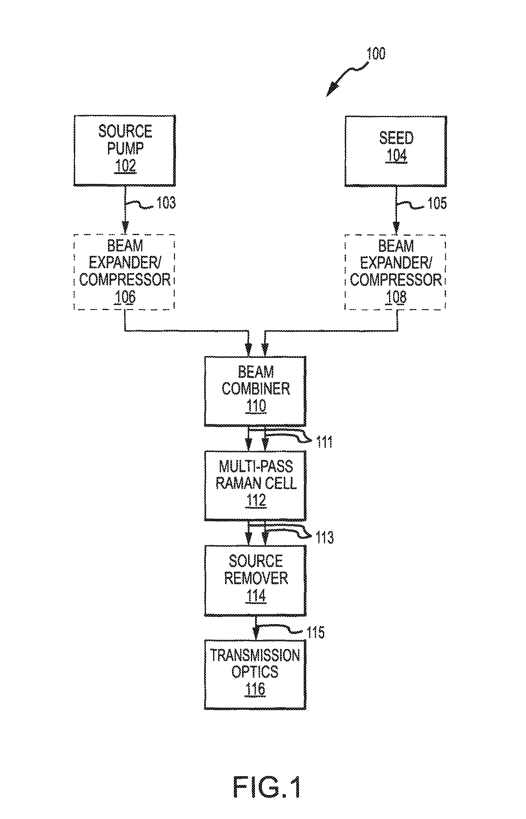
system includes: a source for transmitting a source beam; a Raman cell for wavelength shifting the source beam, where the cell has an input port (e.g., an entry window) for receiving the source beam into the cell and an exit port (e.g., an exit window) for transmitting the source beam from the cell; and optics for forming the beam such that the
energy density at the exit port is greater than at the input port. For example, the optics may be disposed between the source and the cell and may have an effective
focal length that is greater than the distance from the optics to the exit port (measured along the
optical path of the beam, which may be folded) and less than infinity.

