Automatic Gain Control Based on Bandwidth and Delay Spread

a gain control and delay spread technology, applied in the direction of amplification control, digital transmission, electrical equipment, etc., can solve the problems of reducing the headroom, introducing quantization errors, and reducing the so as to reduce the amount of signal variation, bandwidth and/or delay spread, the effect of increasing the bandwidth

Active Publication Date: 2010-07-29
TELEFON AB LM ERICSSON (PUBL)
View PDF20 Cites 108 Cited by
  • Summary
  • Abstract
  • Description
  • Claims
  • Application Information

AI Technical Summary

Benefits of technology

[0006]The present invention relates to gain control for a receiver in a wireless communication system. The delay spread of a wireless channel and bandwidth of a received signal are used to derive an estimate of the expected signal variation due to fast fading. Typically, the amount of signal variation due to fast fading will decrease as the bandwidth and / or delay spread increase. When the expected signal variation decreases, the gain control circuit adjusts the signal level of the received signal upward to reduce the headroom so that the dynamic range of receiver components is used efficiently. Conversely, when the expected signal variation increases, the gain control circuit adjusts the signal level downward to increase headroom so that clipping is avoided. Adjustments to the signal level are thus made to avoid clipping while at the same time ensuring that the dynamic range of receiver components are efficiently utilized.

Problems solved by technology

Converting the signal to the digital domain implies that some quantization error is introduced.
If the signal level if too high, the overflow will distort (clip) the signal.
In this case, the quantization error will be larger than necessary.
Analog components within a receiver have clipping or saturation levels (and possibly an intermediate region contributing with significant nonlinear distortion) that limits its signal strength operation upwards.
Downwards, analog circuits are limited by noise generated by the devices within the circuits.

Method used


Image

  • Automatic Gain Control Based on Bandwidth and Delay Spread
  • Automatic Gain Control Based on Bandwidth and Delay Spread
  • Automatic Gain Control Based on Bandwidth and Delay Spread

Examples


Embodiment Construction

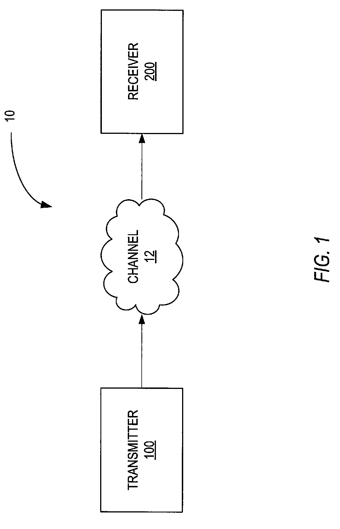
[0022]Referring now to the drawings, FIG. 1 illustrates in simplified form a communication system indicated generally by the numeral 10. Communication network 10 may, for example, comprise a wireless communication system such as Wireless LAN or mobile communication network operating according to any standard now known or later developed, such as the Wideband Code Division Multiple Access (WCDMA) standard and the Long Term Evolution (LTE) standard. The communication network 10 includes a transmitter 100 and a receiver 200. Transmitter 100 transmits information over a communication channel 12 to receiver 200. Those skilled in the art will appreciate that transmitter 100 and receiver 200 may be part of a communication device having both a transmitter 100 and a receiver 200. The transmitter 100 may be included in a base station 100 in a mobile communication network, and the receiver 200 may be included in a user equipment in a wireless communication network, or vice versa. The present i...


PUM


Abstract

A gain control circuit adjusts the signal level of a received signal responsive to the bandwidth a received signal and / or the delay spread of the channel in which the signal has propagated. The bandwidth and delay spread are evaluated to estimate the amount of signal variation that is expected due to fast fading. Adjustments to the signal level are then made to avoid clipping while at the same time ensuring that the dynamic range of a receiver component is efficiently utilized.

Description

BACKGROUND[0001]The present invention relates generally to gain control for a receiver in a wireless communication system and, more particularly, to gain control circuit that varies a signal level in a receiver to prevent clipping or saturation effects.[0002]Gain controllers, like automatic gain controllers (AGC) are widely used in wireless communication receivers as a means for reducing the dynamic range requirements of receiver components, such as amplifiers, filters, mixers, analog-to-digital converters, and digital baseband processors. More particularly, the AGC controls the gain of one or more variable-gain-amplifiers (VGA) such that the signal strength in subsequent stages of the receiver are not forced into saturation or clipping levels while at the same time maintaining a maximum signal-to-noise ratio (SNR) for the signal of interest. The AGC may, for instance, try to keep the average signal level a certain amount below the clipping levels (e.g., 10 dB) to provide headroom f...

Claims


Application Information

Patent Timeline
Patent Type & Authority Applications(United States)
IPC IPC(8): H04L27/08H04B17/40
CPCH03G3/3078H03G3/3068
Inventor WILHELMSSON, LEIFCELANDER, JANSUNDSTROM, LARS
Owner TELEFON AB LM ERICSSON (PUBL)
Why Eureka
Try Eureka