
Dual tir prism architecture to enhance dlp projectors

Active Publication Date: 2010-07-29
BARCO NV
View PDF14 Cites 24 Cited by
  • Summary
  • Abstract
  • Description
  • Claims
  • Application Information

AI Technical Summary

Benefits of technology

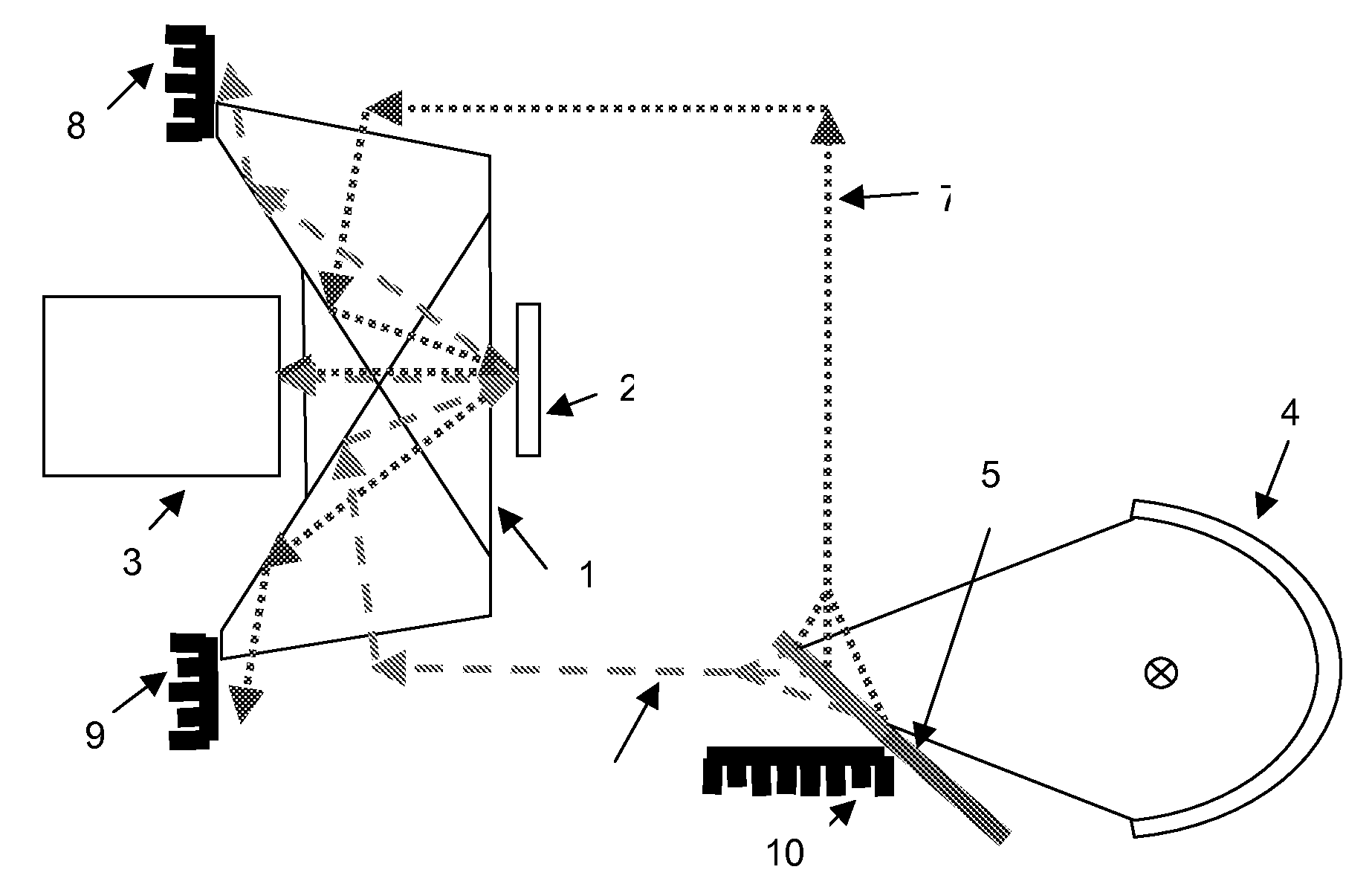
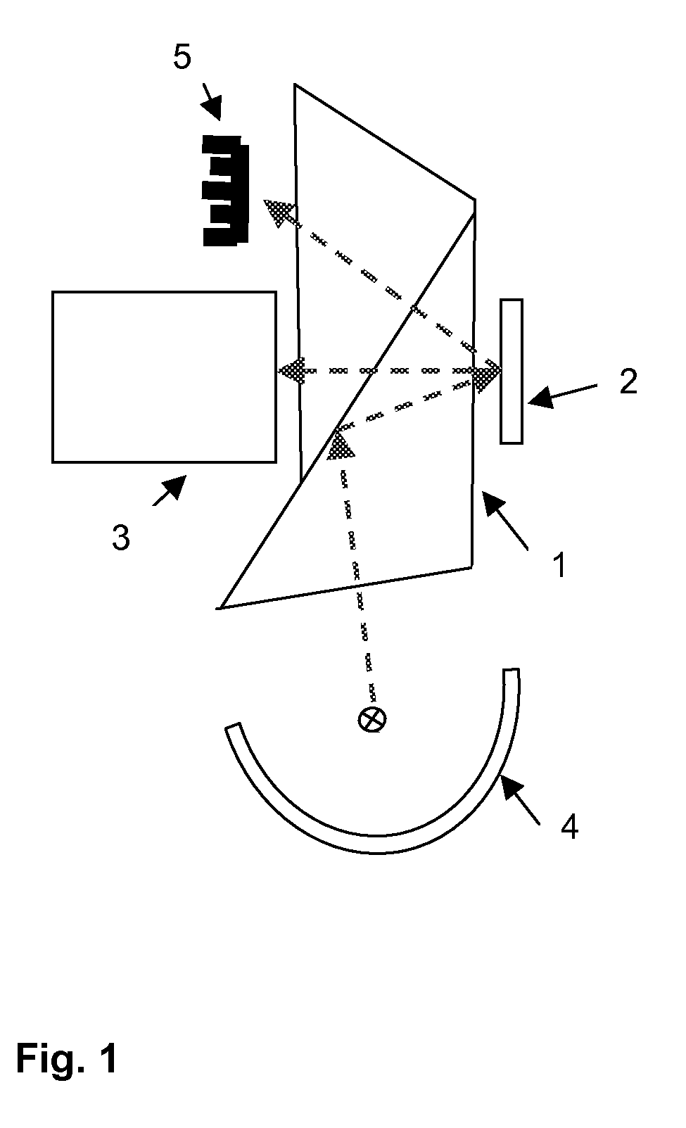
[0008]It is an object of the present invention to provide good methods and systems for displaying. It is an advantage of embodiments according to the present invention that the performance of a DLP™ projection system can be increased. In some embodiments the latter may be done by offering a solution to combine 2 light paths to contribute to the brightness on the screen. In other embodiments this may be by offering a good way of removing unwanted light from the system.
[0016]In one exemplary implementation those two light paths can be collecting light from 2 different light sources which are driven in a pulsed manner with a duty cycle of approximately 50% at increased power. To create a white image the DMD will sequentially direct the light of the first light source to the projection lens when this first lamp is active or direct the light of the second light source to the projection lens when the second light source is active. In this sequential mode of operation the light sources can be combined without increasing the etendue such that the efficiency from the combination of the lamps is as good as the efficiency of a single lamp and the light output can be effectively doubled compared to a single lamp system. The combination is made without the introduction of additional moving elements or polarization switching elements. The DMD is serving simultaneously as the light switch to select the active light source, and as the imaging device. This approach can be applied to both single-chip and 3-chip DLP™ projectors.
[0018]A special colour transformation algorithm is proposed to transform the image input signals to make optimal use of the capabilities offered by the second implementation, and create maximum colour saturation of the image.

Problems solved by technology

Especially for higher power lamps such a smaller arc gap cannot be achieved unless at the cost of a significant reduction of the lamp life.
However the brightness of the pure primary (red, green and blue) colours and pure secondary (yellow, cyan and magenta) colours obtained thereby remains unchanged, so that adding a white segment results in a loss of colour saturation.
The suggested solutions however require the use of additional moving elements or switchable retarders, both difficult to implement especially with large and high power lamp light sources.
Also the implementation suggested with the switchable retarders relies on the polarization of the light source, a solution that is only efficient when the display device operation is based on the use of polarized light, which is not the case for DLP™ projection technology.

Method used


Image

  • Dual tir prism architecture to enhance dlp projectors
  • Dual tir prism architecture to enhance dlp projectors
  • Dual tir prism architecture to enhance dlp projectors

Examples


Embodiment Construction

[0026]The present invention will be described with respect to particular embodiments and with reference to certain drawings but the invention is not limited thereto but only by the claims. The drawings described are only schematic and are non-limiting. In the drawings, the size of some of the elements may be exaggerated and not drawn on scale for illustrative purposes.

[0027]Furthermore, the terms first, second, third and the like in the description and in the claims, are used for distinguishing between similar elements and not necessarily for describing a sequential or chronological order. It is to be understood that the terms so used are interchangeable under appropriate circumstances and that the embodiments of the invention described herein are capable of operation in other sequences than described or illustrated herein.

[0028]Moreover, the terms top, bottom, over, under and the like in the description and the claims are used for descriptive purposes and not necessarily for descri...


PUM


Abstract

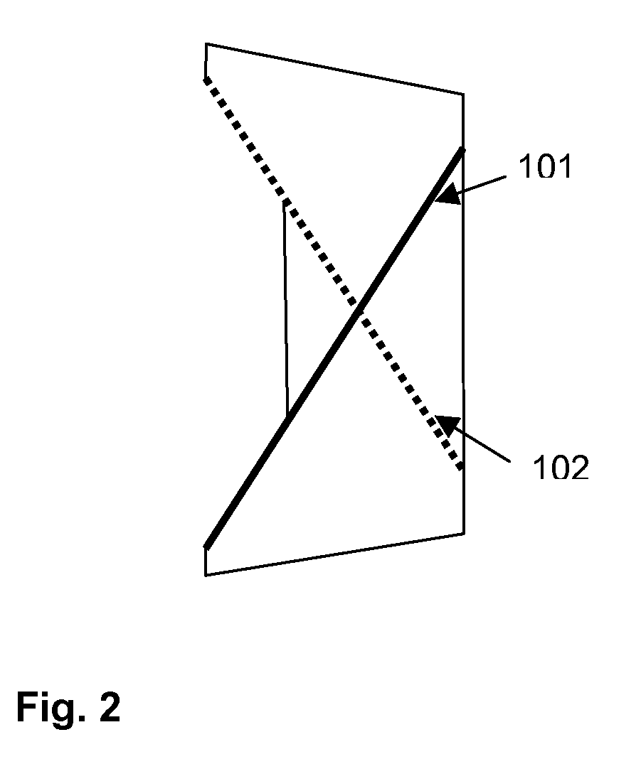
A projection system incorporating a prism with dual total internal reflection function, to increase the performance of DLP™ projection, by offering a solution to combine 2 light paths to contribute to the brightness on the screen and at the same time rejecting flat-state and off-state light from entering the projection lens thereby enhancing contrast. In one implementation those two light paths can be collecting light from 2 different light sources which are driven in a pulsed manner with a duty cycle of approximately 50% for each of the two light sources at increased power. In a second implementation with a colour sequential single DMD™ projector, while one light path passes a primary colour the second light path passes the complementary secondary colour. A special colour transformation algorithm is proposed to transform the image input signals to make optimal use of the capabilities offered by the second implementation, and create maximum brightness and colour saturation of the image.

Description

[0001]The present invention is in the technical field of projector illumination technology and in particular relates to methods, apparatus and controllers for projection systems.BACKGROUND OF THE INVENTION[0002]Efficient use of the light source, in most cases an arc lamp is important for cost efficient implementation of high brightness projectors. The use of ever smaller micro-displays creates a demand for light sources with a lower etendue, or in the case of an arc lamp a smaller arc gap. Especially for higher power lamps such a smaller arc gap cannot be achieved unless at the cost of a significant reduction of the lamp life. When combining multiple light sources to increase the brightness the etendue of the light sources add up so that efficiency drops and the effective brightness increase from adding a light source is less then the expected multiple of a single light source output.[0003]More particularly, the present invention is in the technical field of DLP™ projection technolo...

Claims


Application Information

Patent Timeline
IPC IPC(8): G06K9/00G03B21/28
CPCH04N5/7458H04N9/3197H04N9/3164
Inventor MAES, DIRK L.A.
Owner BARCO NV
Learn More