Perpendicular magnetic recording medium and perpendicular magnetic recording medium manufacturing method

Active Publication Date: 2010-07-29
WESTERN DIGITAL TECH INC
View PDF10 Cites 76 Cited by
  • Summary
  • Abstract
  • Description
  • Claims
  • Application Information

AI Technical Summary

Benefits of technology

[0031]According to a magnetic recording medium of this invention, a reinforcing layer is provided between a main recording layer and a continuous layer so that it is possible to improve

Problems solved by technology

However, in the case of conventionally commercialized magnetic disks of the in-plane magnetic recording type (also called the longitudinal magnetic recording type or the horizontal magnetic recording type), as a result of the reduction in size of magnetic crystal grains, there h

Method used


Image

  • Perpendicular magnetic recording medium and perpendicular magnetic recording medium manufacturing method
  • Perpendicular magnetic recording medium and perpendicular magnetic recording medium manufacturing method
  • Perpendicular magnetic recording medium and perpendicular magnetic recording medium manufacturing method

Examples


example 1

[0070]Herein, an amorphous aluminosilicate glass was molded into a disk shape by direct press, thereby producing a glass disk. This glass disk was ground, polished, and chemically strengthened in sequence, thereby obtaining a smooth nonmagnetic disk substrate in the form of a chemically strengthened glass disk. The glass substrate was a 2.5-inch magnetic disk substrate having a diameter of 65 mm, an inner diameter of 20 mm, and a disk thickness of 0.635 mm. Herein, the surface roughness of the obtained glass substrate was measured by an AFM (atomic force microscope) and it was confirmed to be a smooth surface with Rmax of 2.18 nm and Ra of 0.18 nm. Rmax and Ra follow Japanese Industrial Standard (JIS).

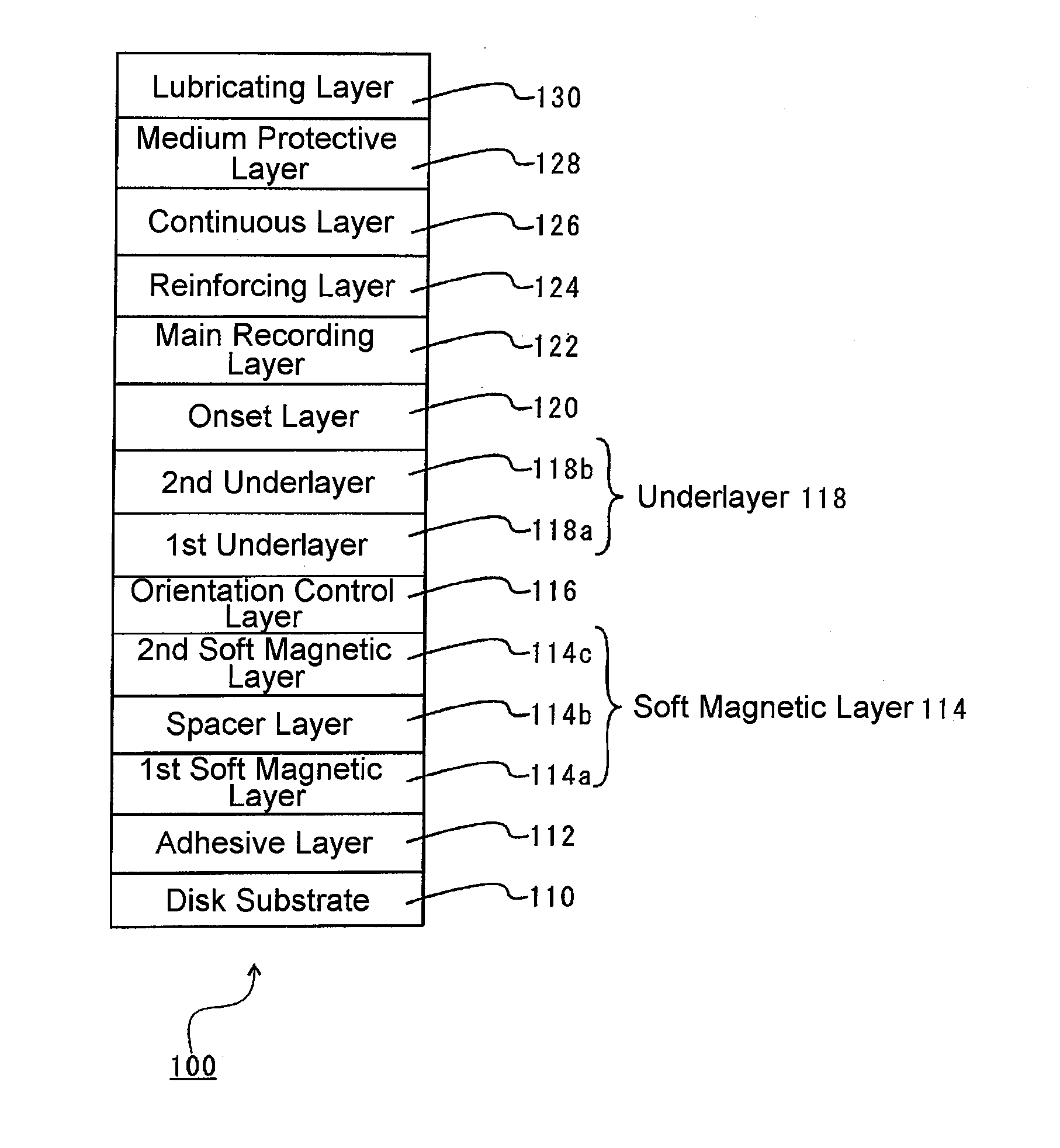
[0071]Then, using a sputtering film forming apparatus, the adhesive layer 112, the soft magnetic layer 114, the orientation control layer 116, the underlayer 118, the onset layer 120, and the main recording layer 122 were formed in sequence on the disk substrate 110 by DC magnetron spu...

example 2

[0084]The BER depends on not only the thickness of the reinforcing layer 124 described above, but also the thickness of the continuous layer 126.

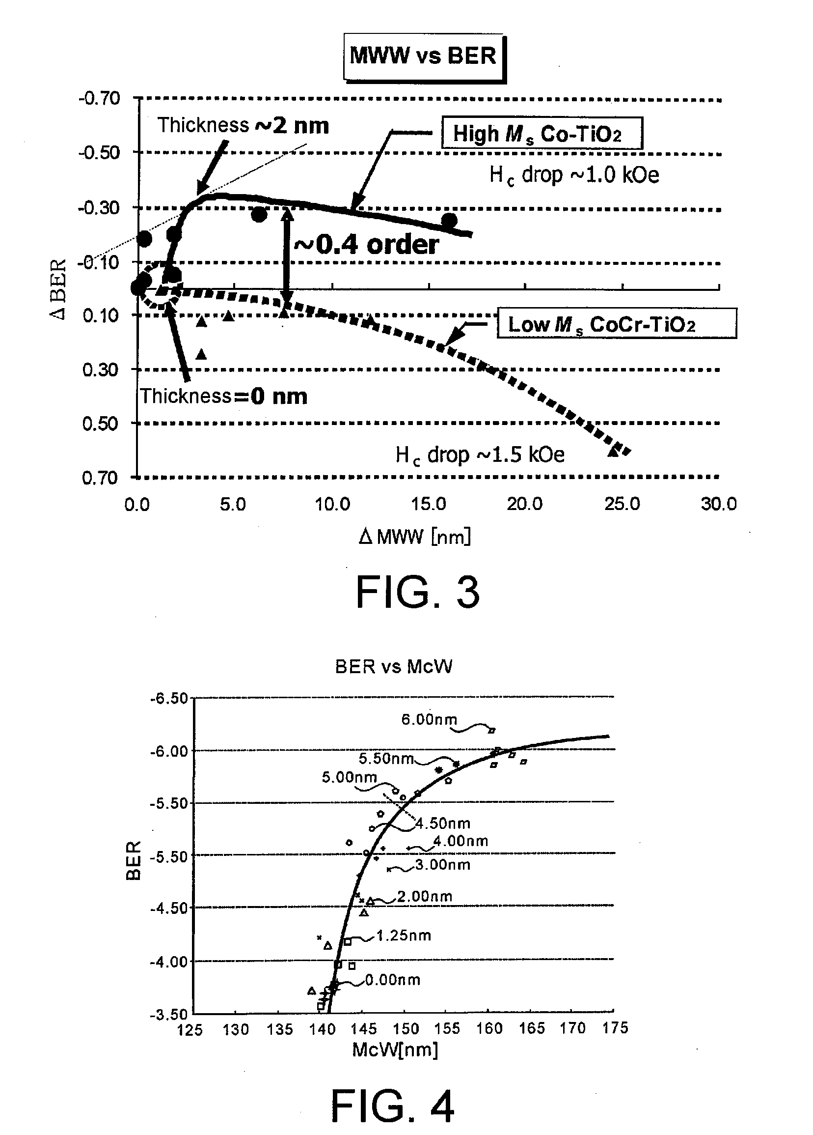
[0085]FIG. 4 shows the relationship between McW and BER obtained by changing the thickness of the continuous layer 126 using the basic structure shown in Example 1. Herein, the McW is the sum of the recording track width MWW and the write fringing (erase width). In this event, the thickness of the main recording layer 122 was 12 nm.

[0086]Referring to FIG. 4, when the thickness of the continuous layer is 5 nm or less, it is possible to obtain a sharp improvement in BER with respect to an increase in McW. In a region where the thickness is 5 nm or more and 10 nm or less, although an improvement in BER is expected, an increase in McW is also induced. Therefore, the continuous layer 126 is set to 10 nm or less, preferably 5 nm or less.

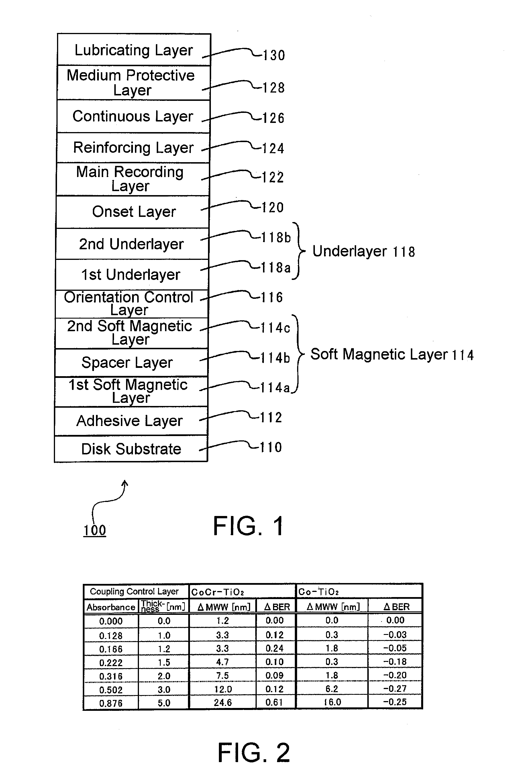
[0087]From Example 1 and Example 2 described above, when the reinforcing layer 124 is 2 nm or less and the cont...

example 3

[0088]In this embodiment, when Co—TiO2 is inserted as the reinforcing layer 124, there is also exhibited an effect that the erase width is also reduced.

[0089]FIG. 5 shows the relationship between the thickness of the reinforcing layer 124 and the normalized write fringing amount ((McW-MWW) / MWW). According to FIG. 5, in a range in which Hc of the perpendicular magnetic recording medium 100 does not decrease, if the thickness of the reinforcing layer 124 is increased, the normalized fringing amount, i.e. the erase width, decreases without causing a change in BER. The results of this qualitatively agree with the LLG calculation results.

[0090]According to the perpendicular magnetic recording medium 100 described above, the reinforcing layer 124 is provided between the main recording layer 122 and the continuous layer 126 so that it is possible to improve the S / N ratio of the perpendicular magnetic recording medium 100 and to reduce the write fringing by the new configuration. Therefore,...


PUM


Abstract

[Problems] To provide a reinforcing layer between a main recording layer and a continuous layer so as to improve the S/N ratio of a magnetic recording medium and reduce the write fringing effect by the new configuration.
[Means for Solving Problems] A perpendicular magnetic recording medium (100) includes a substrate (110), and a main recording layer (122), a reinforcing layer (124), and a continuous layer (126) which are overlaid in this order on the substrate. The reinforcing layer (124) has a granular structure. The saturation magnetization Ms of the reinforcing layer (124) is higher than the saturation magnetization of the main recording layer (122).

Description

TECHNICAL FIELD[0001]This invention relates to a perpendicular magnetic recording medium adapted to be mounted in a HDD (hard disk drive) or the like and to a method of manufacturing the perpendicular magnetic recording medium.BACKGROUND ART[0002]Various information recording techniques have been developed following the increase in volume of information processing in recent years. Particularly, the recording density of HDDs using the magnetic recording technique has been increasing more and more. In order to achieve the high recording density in a magnetic disk for use in a HDD or the like, it is necessary to reduce the size of magnetic crystal grains forming a main recording layer serving to record information signals, and further, to reduce the thickness of the layer. However, in the case of conventionally commercialized magnetic disks of the in-plane magnetic recording type (also called the longitudinal magnetic recording type or the horizontal magnetic recording type), as a resu...

Claims


Application Information

Patent Timeline
IPC IPC(8): G11B5/66G11B5/84
CPCG11B5/66G11B5/656G11B5/7325G11B5/667G11B5/73921G11B5/7369G11B5/736G11B5/737G11B5/674
Inventor SONOBE, YOSHIAKIKIM, KONG
Owner WESTERN DIGITAL TECH INC
Why Eureka
Try Eureka