Electromagnetic device having compact flux paths for harvesting energy from vibrations

a technology of electromagnetic devices and flux paths, which is applied in the field of electromagnetic devices having compact flux paths for harvesting energy from vibrations, can solve the problems of limited equipment operation distance, small available volume in borehole environment, and limited energy storage capacity of batteries having relatively large storage capacity, so as to improve the coupling of energy, enhance the compactness of the path traversed, and enhance the flexibility of the adapting device form factor

Inactive Publication Date: 2010-08-05
SCHLUMBERGER TECH CORP +1
View PDF30 Cites 75 Cited by
  • Summary
  • Abstract
  • Description
  • Claims
  • Application Information

AI Technical Summary

Benefits of technology

[0008]One advantage of the invention is that it can be used to implement a device for generating a given level of electrical energy output in a smaller volume of space for a given vibrational input. Unlike the typical prior art designs, the polarization axis, of the magnets is perpendicular to the direction of relative motion, and also perpendicular to a surface defined by the coils. Further, the magnets are arranged so that adjacent magnets are characterized by opposite polarizations (illustrated with S and N). Magnetically permeable plates may be employed to further enhance the compactness of the path traversed by lines of magnetic flux. This configuration provides improved coupling of energy from the relative motion between magnets and coils relative to the prior art. This is an advantage for downhole applications where space is limited.
[0009]Another advantage of the invention is enhanced flexibility in adapting device form factor to particular shapes. A relatively flat device may be implemented using flexures, i.e., compact structures made up of beams arranged in a zig-zag or other pattern to support the magnets and coils on a printed circuit. The flexures may also function as spring members that define the resonant frequency of the device. The flexures can be appropriately designed to reduce the movement of the magnets in other directions. Alternative embodiments may be characterized by cylindrical or annular form factors. For example, the coils and magnets may be controlled in an arcuate motion rather than a linear motion. Alternatively, radially polarized annular ring magnets may be used.

Problems solved by technology

One of the technical challenges to performing tasks in such remote locations is providing power to equipment.
However, both of these techniques have disadvantages.
For example, a wireline connection to the surface limits the distance at which the equipment can operate relative to the energy source because there are practical limits to the length of a wireline connection.
Using stored energy avoids some of the disadvantages of using a wireline connection to the surface, but relatively little energy can be stored because of size limitations.
For example, the available volume in a borehole environment is relatively small for a battery having relatively large storage capacity.
However, propellers and turbines are typically not robust enough to operate reliably in the downhole environment over long periods of time.
One limitation of the design is that the amplitude of magnet movement must be similar to the length of the coil in order to generate appreciable changes in magnetic flux through the coil.
Because the dimensions of the device for a given level of output are limited by this feature, it may not be practical to generate sufficient electrical power in the borehole environment with such a design.
However, the induced currents from each magnet could be in direct opposition depending on the motion of the individual magnets, thereby reducing the net current at the ends of the coil.
Additionally, the axis of polarization of the magnets is parallel to the direction of relative motion, thereby limiting the effective coupling and compactness for a given level of output.
Further, the axis of polarization of the magnets is parallel to the direction of relative motion, thereby limiting effective coupling and compactness for a given level of output.

Method used


Image

  • Electromagnetic device having compact flux paths for harvesting energy from vibrations
  • Electromagnetic device having compact flux paths for harvesting energy from vibrations
  • Electromagnetic device having compact flux paths for harvesting energy from vibrations

Examples


Embodiment Construction

[0020]The particulars described herein are for purposes of discussion of the illustrated embodiments of the present invention in order to provide what is believed to be a useful and readily understood description of the principles and conceptual aspects of the invention. No attempt is made to show structural aspects of the invention in more detail than is necessary for a fundamental understanding of the invention. The invention may be implemented in various different embodiments of a device for converting kinetic energy from the surrounding environment into electrical energy. The embodiments are described below in the context of the source of kinetic energy being vibrations of a drilling tool such as those associated with drilling oil wells. However, the invention is not limited to petrochemical wells.

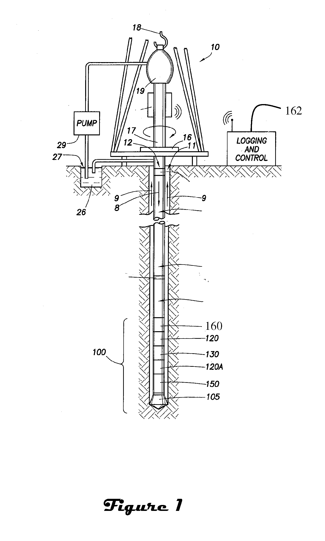
[0021]FIG. 1 illustrates a wellsite system in which the present invention can be employed. The wellsite can be onshore or offshore. In this exemplary system, a borehole (11) is formed ...


PUM


Abstract

Electrical energy is produced by harvesting mechanical energy in the form of vibrations which are generally present in tools during the process of drilling oil wells. Electrical energy production is based on the Faraday induction principle whereby changes, i.e., movement, in magnetic flux through a coil induce an electric current through the coil. The changes in magnetic flux are produced by relative motion between at least one set of magnets and at least one coil. In particular, as the flux lines change due to the movement of the magnets, they remain perpendicular to both the direction of motion of the magnets as well as a planar or cylindrical surface defined by the coils. As a result, output for a given size of device is enhanced. Further, flexibility in adapting device form factor to particular shapes is enhanced. For example, a relatively flat device may be implemented using flexural bearing support of the magnets and coils on a printed circuit. The flexural bearings may also function as spring members that define the resonant frequency of the device. Alternative embodiments may be characterized by cylindrical or annular form factors.

Description

FIELD OF THE INVENTION [0001]This invention is generally related to energy harvesting, and more particularly to converting kinetic energy from flowing fluid into electrical energy to power equipment in a remote location.BACKGROUND OF THE INVENTION [0002]In order to recover natural resources from subterranean formations it is often necessary to perform tasks related to exploration, monitoring, maintenance and construction in remote locations that are either difficult or impractical for personnel to reach directly. For example, boreholes may be drilled tens of thousands of meters into the earth, and in the case of offshore drilling, the borehole itself may be thousands of meters under water. One of the technical challenges to performing tasks in such remote locations is providing power to equipment. It is known to power downhole and undersea equipment via either stored energy or wireline connection to the surface. However, both of these techniques have disadvantages. For example, a wi...

Claims


Application Information

Patent Timeline
Patent Type & Authority Applications(United States)
IPC IPC(8): F03G7/08H02K41/035
CPCH02K35/02
Inventor PABON, JAHIR A.GUERRERO, JULIOSIHLER, JOACHIMLANG, JEFFREY H.SLOCUM, ALEXTRIMBLE, ZACHARYMA, HONGSHEN
Owner SCHLUMBERGER TECH CORP
Why Eureka
Try Eureka