Electrical Transformer with Unidirectional Flux Compensation

a technology of electric transformers and flux compensation, which is applied in the direction of transformer/inductance circuits, transformer/inductance details, electrical devices, etc., can solve the problems of increasing magnetic losses, major distortions of magnetizing current, and current components that superimpose themselves on the operating current of the transformer

Active Publication Date: 2010-08-05
SIEMENS ENERGY GLOBAL GMBH & CO KG
View PDF21 Cites 37 Cited by
  • Summary
  • Abstract
  • Description
  • Claims
  • Application Information

AI Technical Summary

Problems solved by technology

It is known that in the case of an electrical transformer operated in conjunction with a converter, a current component that superimposes itself on the operating current of the transformer can arise owing to inaccuracies in driving the power semiconductor switches.
Because of the high permeability of the ferromagnetic core material, even a small unidirectional flux component can cause the core to be saturated and result in major distortions in the magnetizing current.
The consequences of said asymmetric adjusting are increased magnetic losses and hence increased heating of the core, as well as peaks in the magnetizing current that cause increased emission of operating noise.
Since, however, the former approach will increase the transformer's structural volume and the latter will result in a greater magnetizing current, both approaches are disadvantageous.
However, said actuators consume a not inconsiderable amount of energy during operation and are moreover interference-prone and costly.

Method used


Image

  • Electrical Transformer with Unidirectional Flux Compensation
  • Electrical Transformer with Unidirectional Flux Compensation
  • Electrical Transformer with Unidirectional Flux Compensation

Examples


Embodiment Construction

[0005]An object of the present invention is to provide a transformer in the case of which heating of the core due to a magnetic unidirectional flux therein and the emission of noise will in as simple a manner as possible be lessened.

[0006]Said object is achieved by means of the features of claim 1. Advantageous embodiments of the invention are defined in the dependent claims.

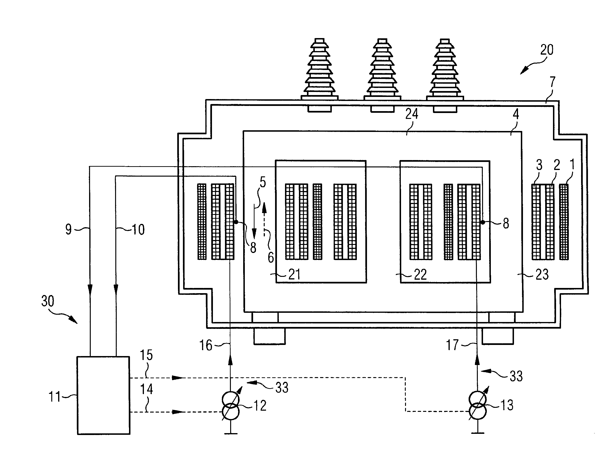
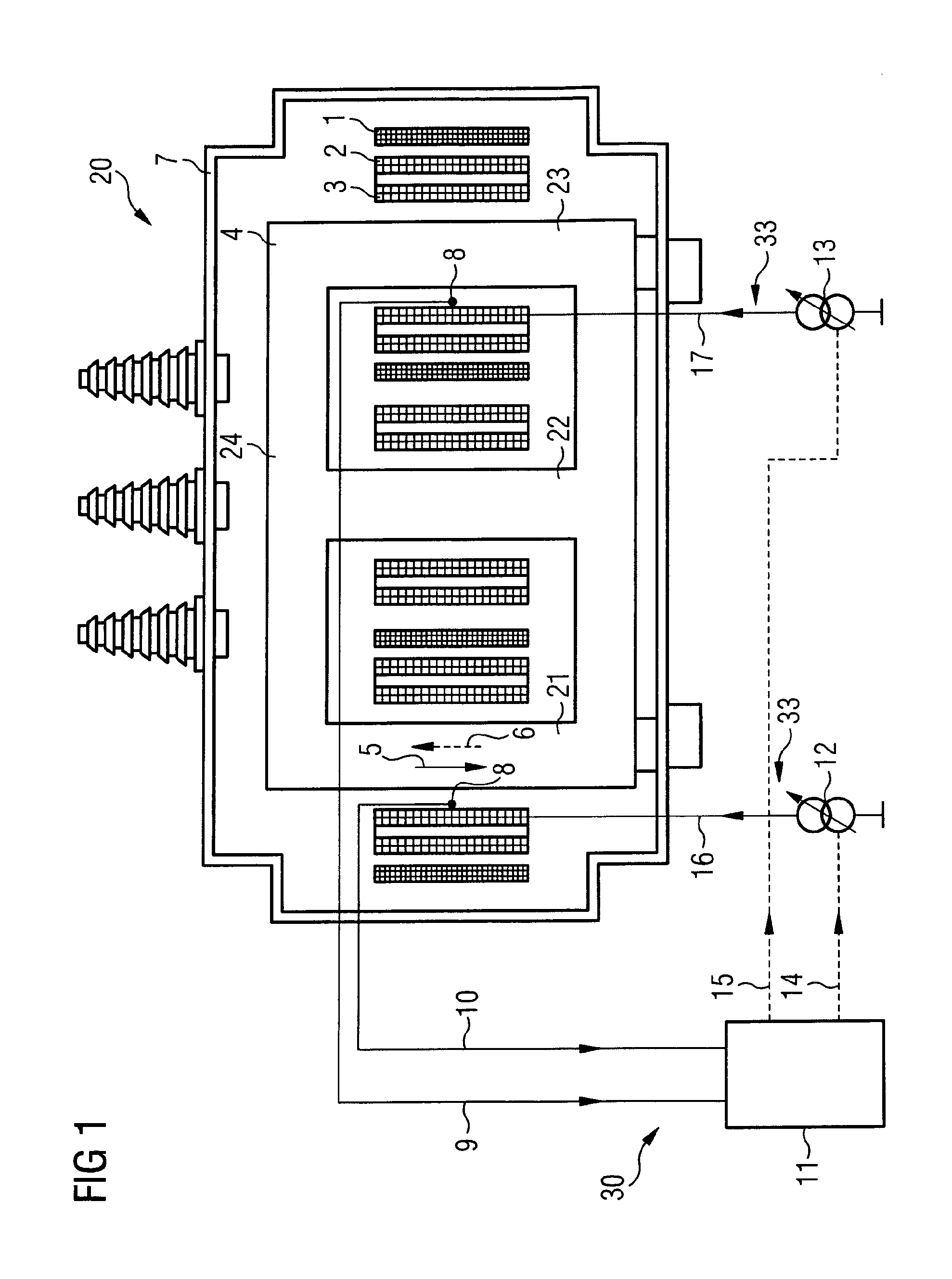
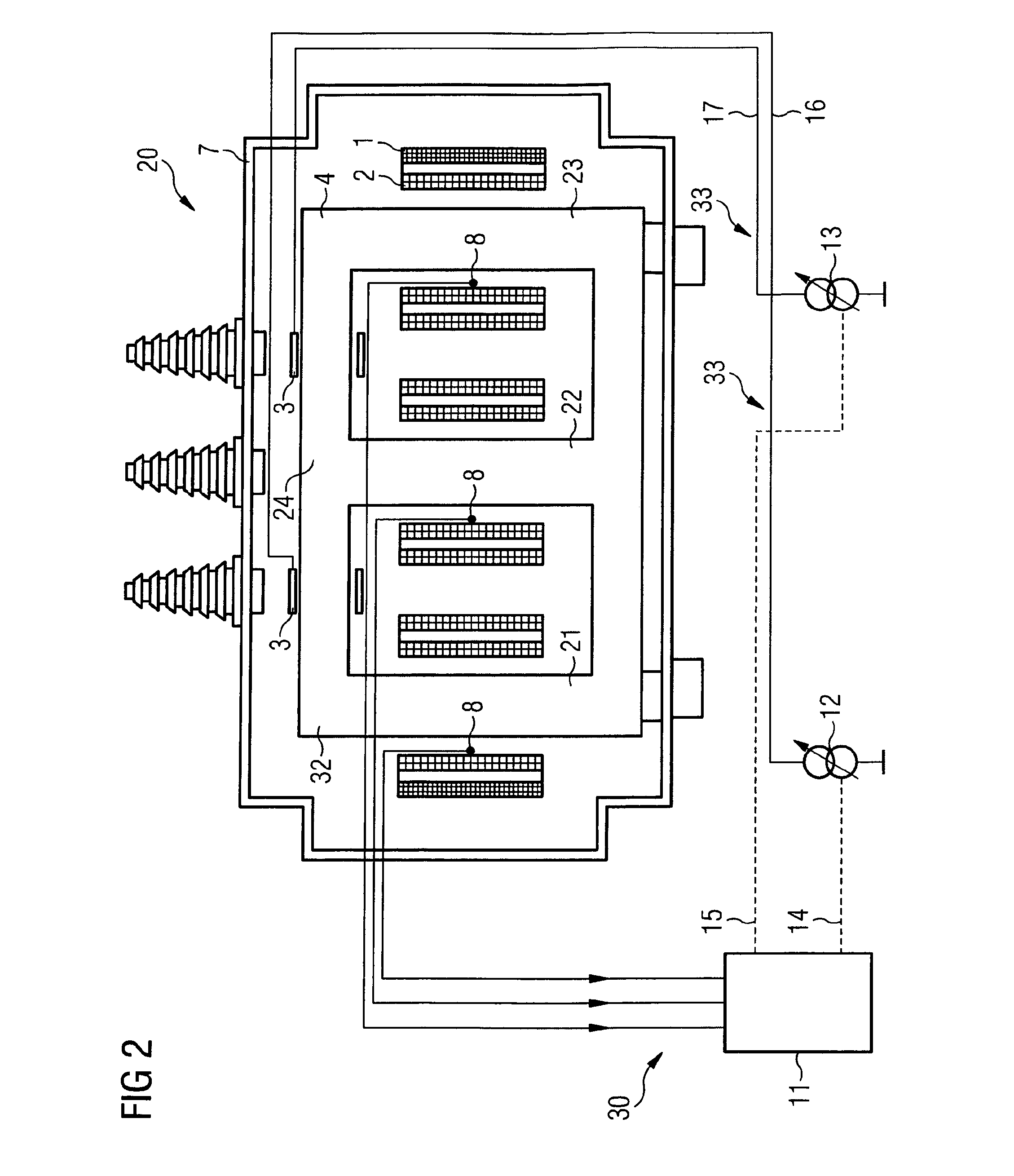
[0007]The invention proceeds from the notion not of combating the undesired effects of pre-magnetizing but of eliminating their cause. The inventive transformer is characterized as follows:

[0008]The transformer has a soft-magnetic core on which, in addition to a primary and secondary winding arrangement, a compensation winding arrangement is arranged.

[0009]The compensation winding arrangement is connected to a current control device that feeds a compensation current into the compensation winding arrangement in accordance with a control variable, which a magnetic field measuring device provides from a measurement...


PUM

PropertyMeasurementUnit
voltageaaaaaaaaaa
voltageaaaaaaaaaa
diameteraaaaaaaaaa

Abstract

transformer includes a soft magnetic core on which a primary winding arrangement, a secondary winding arrangement, and a compensation winding arrangement are arranged. The compensation winding arrangement is connected to a current control device which feeds a compensation current into the compensation winding arrangement using a control signal. A magnetic field measuring device measures the magnetic field in the core of the transformer or the stray magnetic field that closes outside the core via an air path and provides the control signal.

Description

TECHNICAL FIELD [0001]The invention relates to an electrical transformer with unidirectional flux compensation.PRIOR ART [0002]It is known that in the case of an electrical transformer operated in conjunction with a converter, a current component that superimposes itself on the operating current of the transformer can arise owing to inaccuracies in driving the power semiconductor switches. Said current component, which can in terms of the power supply system be regarded as direct current, will be referred to below also as a “direct-current component” or “d.c. component”. Although usually amounting to just a few parts per thousand of the nominal transformer current, in the core of the transformer it produces a magnetic unidirectional flux that is superimposed on the primary or, as the case may be, secondary alternating flux and results in asymmetric adjusting of the B-H characteristic of the ferromagnetic core material. Because of the high permeability of the ferromagnetic core mater...

Claims


Application Information

Patent Timeline
Patent Type & Authority Applications(United States)
IPC IPC(8): H01F27/38
CPCH01F27/34H01F27/385H01F27/38H01F27/345
Inventor HAMBERGER, PETERLEIKERMOSER, ALBERT
Owner SIEMENS ENERGY GLOBAL GMBH & CO KG
Why Eureka
Try Eureka