
Method for ascertaining the noise emission of an internal combustion engine

a technology of internal combustion engine and noise emission, which is applied in the direction of machines/engines, analogue processes for specific applications, instruments, etc., can solve the problems of critical noise emissions, inability to fully avoid, and inability to detect the noise emission of homogeneous combustion, etc., and achieve the effect of short computation times

Inactive Publication Date: 2008-08-21
ROBERT BOSCH GMBH
View PDF4 Cites 1 Cited by
  • Summary
  • Abstract
  • Description
  • Claims
  • Application Information

AI Technical Summary

Benefits of technology

[0007]Example embodiments of the present invention provide a method for ascertaining the noise emissions of an internal combustion engine which requires short computation times and needs only a simple sensor system.
[0009]This method requires only at least one structure-borne noise sensor which is present in many internal combustion engines anyway and is also significantly more cost-effective than a pressure sensor that is installed in the combustion chamber of the internal combustion engine. Furthermore, the energy of the structure-borne noise in a certain frequency band may be ascertained using relatively few computing operations, so that conventional control units such as those used for controlling an internal combustion engine may take over this function in addition to engine control. This makes it possible to monitor the noise emissions of the internal combustion engine, its combustion noise in particular, in a simple manner and during the operation of the engine. Using the noise emissions thus ascertained, the internal combustion engine may be controlled and regulated by the control unit as a function of the noise emissions and the combustion noise.
[0011]The number of the signals to be processed is thus reduced without the need to accept quality losses in the result in ascertaining the noise emissions.
[0019]This standardization or normalization allows the ascertained noise emissions to be analyzed and further processed in a simple manner and may be used as an input variable in the control unit for controlling and regulating the internal combustion engine.
[0023]It may be provided that the maximum gradient of the structure-borne noise signal is detected during the main combustion and / or during the pilot combustion. This makes it possible to ascertain the noise emissions both during the main combustion and during the pilot combustion as needed or, if no pilot injection and consequently no pilot combustion takes place, to detect only the noise emissions during the main combustion.
[0026]To reduce the load on the control unit, it may be furthermore provided that the method is carried out only when the operating state of the internal combustion engine changes. This method makes use of the realization that critical noise emissions occur in particular when the operating state of the internal combustion engine changes, and in steady-state operation this problem does not appear or at least it is so small that the noise emissions do not need to be permanently ascertained.

Problems solved by technology

However, due to the high ignition delay, homogeneous and partially homogeneous combustions exhibit intolerable noise emissions, which cannot be fully avoided using measures such as an increased exhaust gas recirculation rate or retarded combustion.
Mainly, the transition from a conventional non-homogeneous combustion process to a partially homogeneous or homogeneous combustion process and dynamic changes in the operating state may result in critical noise emissions.
These calculations are very computation-intensive and therefore cannot be implemented in the engine control units normally used today.
In this method as well, merely at least one structure-borne noise sensor is required and the analysis of the structure-borne noise signals ascertained by the at least one structure-borne noise sensor also requires only a relatively low computing power.

Method used


Image

  • Method for ascertaining the noise emission of an internal combustion engine
  • Method for ascertaining the noise emission of an internal combustion engine
  • Method for ascertaining the noise emission of an internal combustion engine

Examples


Embodiment Construction

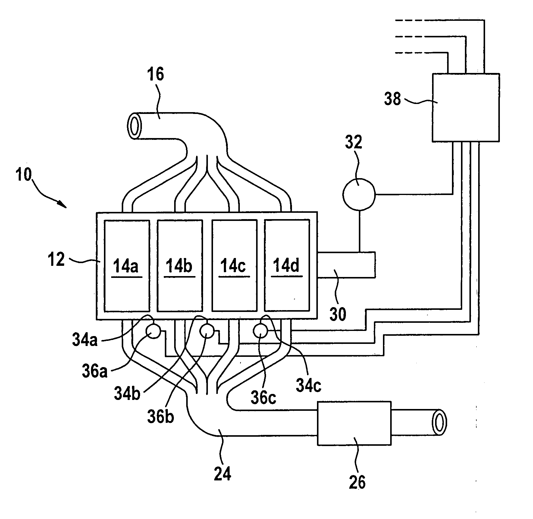
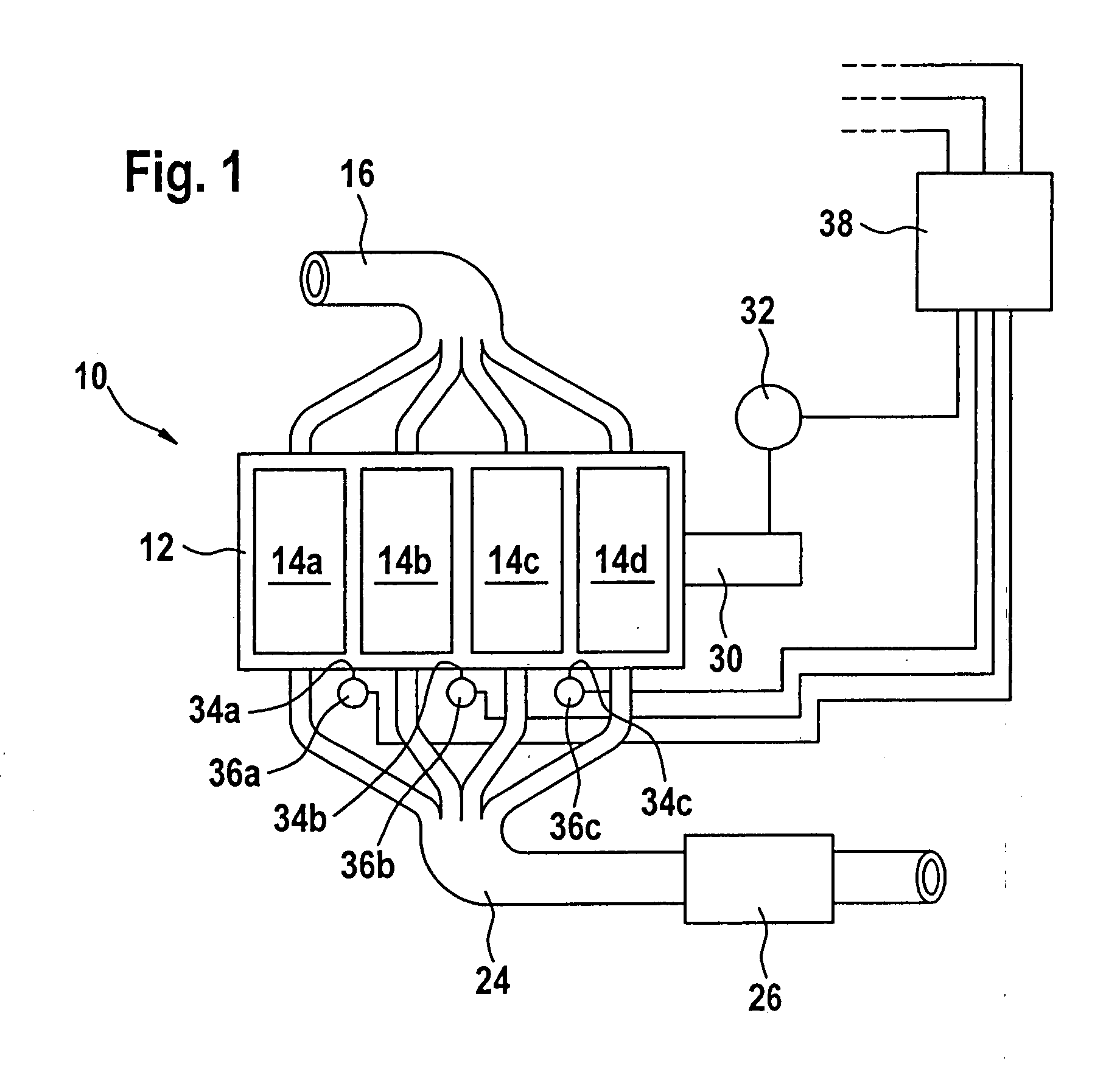
[0033]An internal combustion engine is labeled overall with reference numeral 10 in FIG. 1. It is used for driving a motor vehicle.

[0034]Internal combustion engine 10 includes an engine block 12 having four cylinders 14a to 14d, which receive intake air via an intake manifold 16. Combustion exhaust gases are removed from cylinders 14a through 14d with the aid of an exhaust gas manifold 24, in which a catalytic converter 26 is situated. A crankshaft 30, whose angular position and rotational speed are detected by a speed sensor 32, is set into rotation when engine 10 is operated.

[0035]A first structure-borne noise sensor 36a is situated on engine block 12 between cylinders 14a and 14b at an installation point 34a. A second structure-borne noise sensor 36b is situated between cylinders 14b and 14c at an installation point 34b, and a third structure-borne noise sensor 36c is situated between cylinders 14b and 14c at an installation point 34c.

[0036]All sensors 32 and 36a to 36c deliver ...


PUM


Abstract

Methods for ascertaining the combustion noises of an internal combustion engine need only a structure-borne noise sensor and may be carried out using little computing power.

Description

CROSS-REFERENCE TO RELATED APPLICATIONS[0001]The present application claims priority to Application No. 10 2006 040 656.7, filed in the Federal Republic of Germany on Aug. 30, 2006, which is expressly incorporated herein in its entirety by reference thereto.FIELD OF THE INVENTION[0002]The present invention relates to a method for ascertaining the noise emission of an internal combustion engine.BACKGROUND INFORMATION[0003]Today's internal combustion engines must operate with minimum noise, in addition to low fuel consumption and low emission values.[0004]Mainly in internal combustion engines working by the diesel process, noise emissions should be paid particular attention to. In diesel engines, partially homogeneous and homogeneous combustion processes are used in partial areas of the engine's characteristics map in addition to the conventional, non-homogeneous combustion process in order to achieve minimum emission levels, in particular for nitrogen oxides and soot particles, in th...

Claims


Application Information

Patent Timeline
IPC IPC(8): H04R29/00
CPCG01H1/06
Inventor SCHUELER, MATTHIASKESSLER, MICHAELYOUSSEF, MOHAMEDENGBER, ARNOLDLOEFFLER, AXEL
Owner ROBERT BOSCH GMBH
Learn More