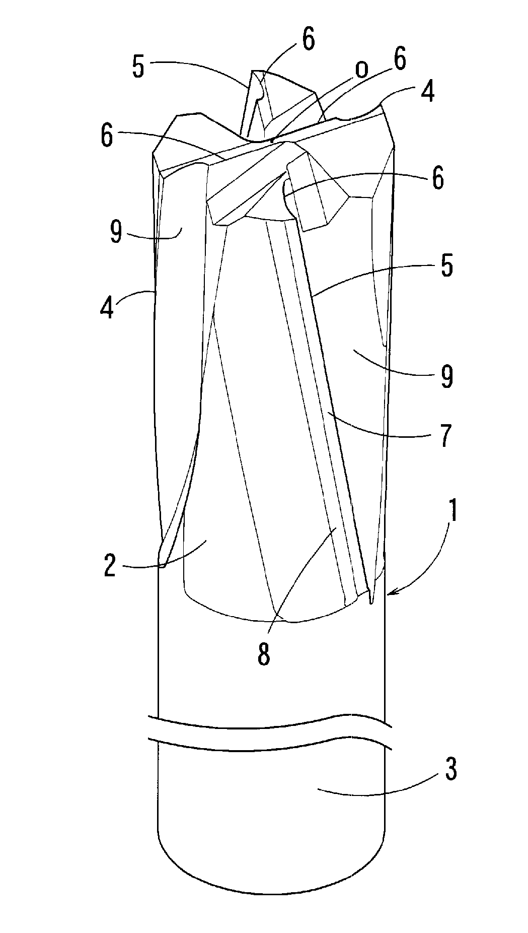
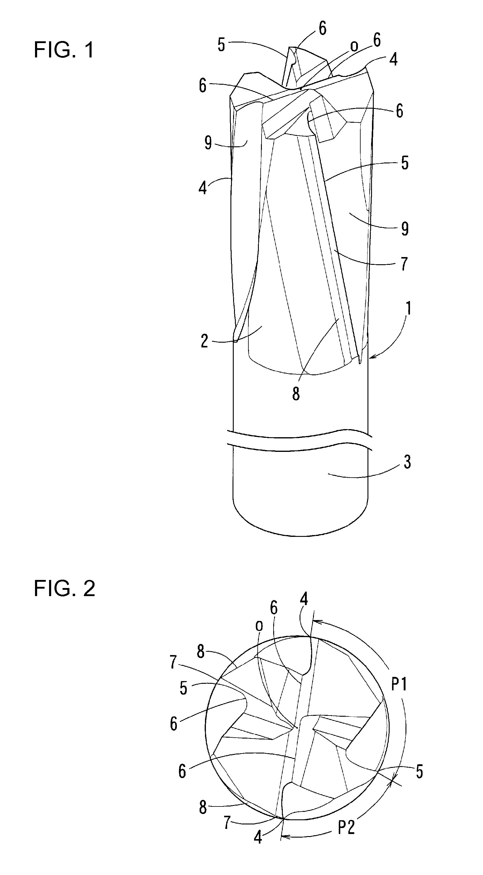
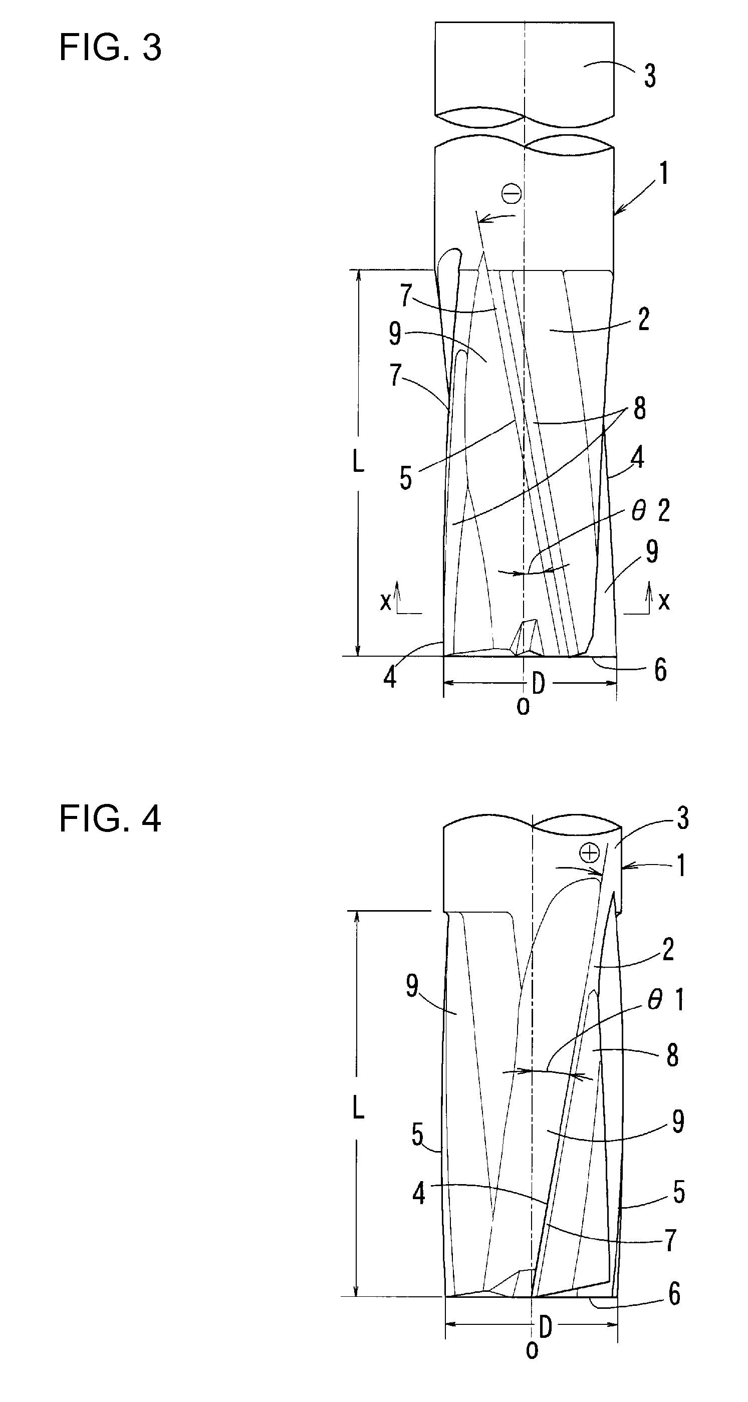
End mill

a technology of end mills and end mills, which is applied in the field of end mills, can solve the problems of short end mill life in cfrp machining, unstable quality of the peripheral portion, and short end mill life, so as to reduce the occurrence of burrs, prevent discontinuous engagement of cutting edges in the workpiece, and smooth cutting.

Active Publication Date: 2010-08-05
SUMITOMO ELECTRIC HARDMETAL CORP
View PDF37 Cites 24 Cited by
  • Summary
  • Abstract
  • Description
  • Claims
  • Application Information

AI Technical Summary

Benefits of technology

[0018]In the end mill according to the present invention, the phase angle (at the tool top) between one of the first cutting edges and its adjacent second cutting edge located toward the back in the tool rotation direction is set to be different from the phase angle (at the tool top) between the second cutting edge and its adjacent first cutting edge located toward the back in the tool rotation direction. Therefore, it is possible to configure each of the first cutting edges and the second cutting edges to be continuous over the effective cutting edge length, the first cutting edges and the second cutting edges, which spiral in opposite directions, not being crossed with each other. By configuring each of the first cutting edges and the second cutting edges to be continuous, cutting proceeds smoothly and discontinuous engagement of the cutting edges in the workpiece can be prevented, thus making the occurrence of burrs difficult. Furthermore, the first cutting edges having a positive helix angle mainly play a role of cutting. When cutting is performed with a cutting edge having a positive helix angle, it is difficult to sufficiently reduce the occurrence of burrs. In particular, burrs easily occur on the upper surface side of the workpiece where a cutting force is applied in a direction opposite to a direction toward the center in the thickness direction of the workpiece. However, even if burrs occur due to cutting with a cutting edge having a positive helix angle, subsequent complementary cutting with a cutting edge having a negative helix angle removes the resulting burrs. Thus, a cut surface having a small number of burrs can be obtained, and high quality machining is made possible.
[0019]Furthermore, the cutting force in the axial direction of each of the cutting edges having a positive helix angle and the cutting force in the axial direction of each of the cutting edges having a negative helix angle are directed in opposite directions and counteract each other. In addition, since the phase angle between one of the first cutting edges and its adjacent second cutting edge located toward the back in the tool rotation direction is set to be different from the phase angle between the second cutting edge and its adjacent first cutting edge located toward the back in the tool rotation direction, the cutting period of each of the first cutting edges is different from the cutting period of each of the second cutting edges. Therefore, chattering during machining does not easily occur, and the occurrence of chipp

Problems solved by technology

In a CFRP panel or the like, a peripheral portion becomes a region having an unstable quality because of the production process.
While the latter method in which an end mill is used is advantageous in that large-scale equipment is not required, an existing processing machine can be used, and the extra peripheral portion can be cut off without preparing pilot holes, a short end-mill life is a problem.
Therefore, even in an end mill coated with a high-hardness co

Method used


Image

  • End mill
  • End mill
  • End mill

Examples


examples

[0071]In order to evaluate the performance of end mills according to the present invention, a four-edged end mill in which the helix angle θ1 of first cutting edges was set at 5° and the helix angle θ2 of second cutting edges was set at −4° and a six-edged end mill in which the helix angles of first cutting edges and second cutting edges were set as above (each being an inventive product having a diameter φ of 12 mm and an effective cutting edge length of 25 mm) were experimentally produced, and their cutting performance was compared with conventional products. As the conventional products, four-edged and six-edged end mills having helix angles of 0° and 30° and having a commonly used shape, and a four-edged end mill in which right-handed helical cutting edges and left-handed helical cutting edges were disposed in a stepped manner in the axial direction so that the upper portion and the lower portion of a region to be machined were cut separately with the two types of cutting edges,...


PUM

PropertyMeasurementUnit
Angleaaaaaaaaaa
Angleaaaaaaaaaa
Angleaaaaaaaaaa

Abstract

It is an object of the present invention to effectively suppress the occurrence of burrs in machining of a fiber-reinforced composite material, etc., using an end mill. An end mill includes first cutting edges 4 which spiral in a direction defining a positive helix angle and second cutting edges 5 which spiral in a direction defining a negative helix angle, the first cutting edges 4 and the second cutting edges 5 being disposed at positions shifted in a circumferential direction. The first cutting edges 4 and the second cutting edges 5 are each configured to be continuous over an effective cutting edge length, and at a tool top, a phase angle P1 between one of the first cutting edges 4 and its adjacent second cutting edge 5 located toward the back in a tool rotation direction is set to be different from a phase angle P2 between the second cutting edge 5 and its adjacent first cutting edge 4 located toward the back in the tool rotation direction.

Description

CROSS-REFERENCE TO RELATED APPLICATION[0001]The present application is a national phase application of PCT Application No. PCT / JP2009 / 055612, filed on Mar. 23, 2009, and claims priority to Japanese Application No. JP2008-089892, filed on Mar. 31, 2008, the entire contents of which are herein incorporated by reference.TECHNICAL FIELD [0002]The present invention relates to end mills used for cutting, slotting, plunging, and the like of fiber-reinforced composite materials typified by fiber-reinforced plastics, metal materials, etc.BACKGROUND ART[0003]Fiber-reinforced composite materials, in particular, carbon fiber-reinforced composite materials (hereinafter referred to as the CFRPs) using carbon fibers are effective in reducing the weight of structures, and their demand has been increasing in airplanes, automobiles, etc. in expectation of improvement in fuel efficiency due to reduction in weight. A CFRP is produced by laminating and integrating layers of a prepreg obtained by impregn...

Claims


Application Information

Patent Timeline
IPC IPC(8): B23C5/10
CPCB23C2226/27Y10T407/196B23C2210/0485Y10T407/1966B23C2210/088B23C5/10B23C2210/0492Y10T407/1948Y10T407/1962B23C2210/54Y10T408/909
Inventor OKA, HISAOSHINO, TATSUYAMAEDA, KAZUO
Owner SUMITOMO ELECTRIC HARDMETAL CORP
Why Eureka
Try Eureka