Furnace and method for producing a discharge lamp

a technology for discharge lamps and furnaces, applied in the direction of electrode system manufacturing, tube/lamp vessel filling, tube/lamp vessel closing, etc., can solve problems such as economic damage, and achieve the effect of strengthening the barrier effect and improving the purity of the volume between the two suction openings

Inactive Publication Date: 2010-08-05
OSRAM GMBH
View PDF5 Cites 0 Cited by
  • Summary
  • Abstract
  • Description
  • Claims
  • Application Information

AI Technical Summary

Benefits of technology

[0022]It is furthermore preferable to connect at least one pump through two suction openings to the first hollow body, in particular one pump respectively at each of the two suction openings. In this case, a first of the suction openings lies closer to the first opening and the second suction opening lies closer to the second opening of the hollow body. Contaminants which enter can at least partially be pumped off through the two suction openings, so that the purity of the volume lying between the two suction openings can be improved further.
[0023]There is preferably a further gas feed between the first suction opening and the first opening, as well as a further gas feed between the second suction opening and the second opening. Argon, helium or neon is preferably introduced from these two gas feeds and may above all be pumped off through the suction opening respectively lying closest, so that a flow acting as a barrier can be formed. Optionally, parts of the gases introduced through the two gas feeds may also escape from the openings of the hollow body, and thus reinforce the barrier effect.

Problems solved by technology

First, this is due to the usually comparatively large interiors of the furnaces used.
Secondly however, depending on the furnace, the discharge gas may also escape from the furnace—this is the case above all with continuous furnaces.
On the one hand this is economically detrimental since some of the gases used, for instance xenon, contribute significantly to the costs of the discharge lamps.

Method used


Image

  • Furnace and method for producing a discharge lamp
  • Furnace and method for producing a discharge lamp
  • Furnace and method for producing a discharge lamp

Examples


Embodiment Construction

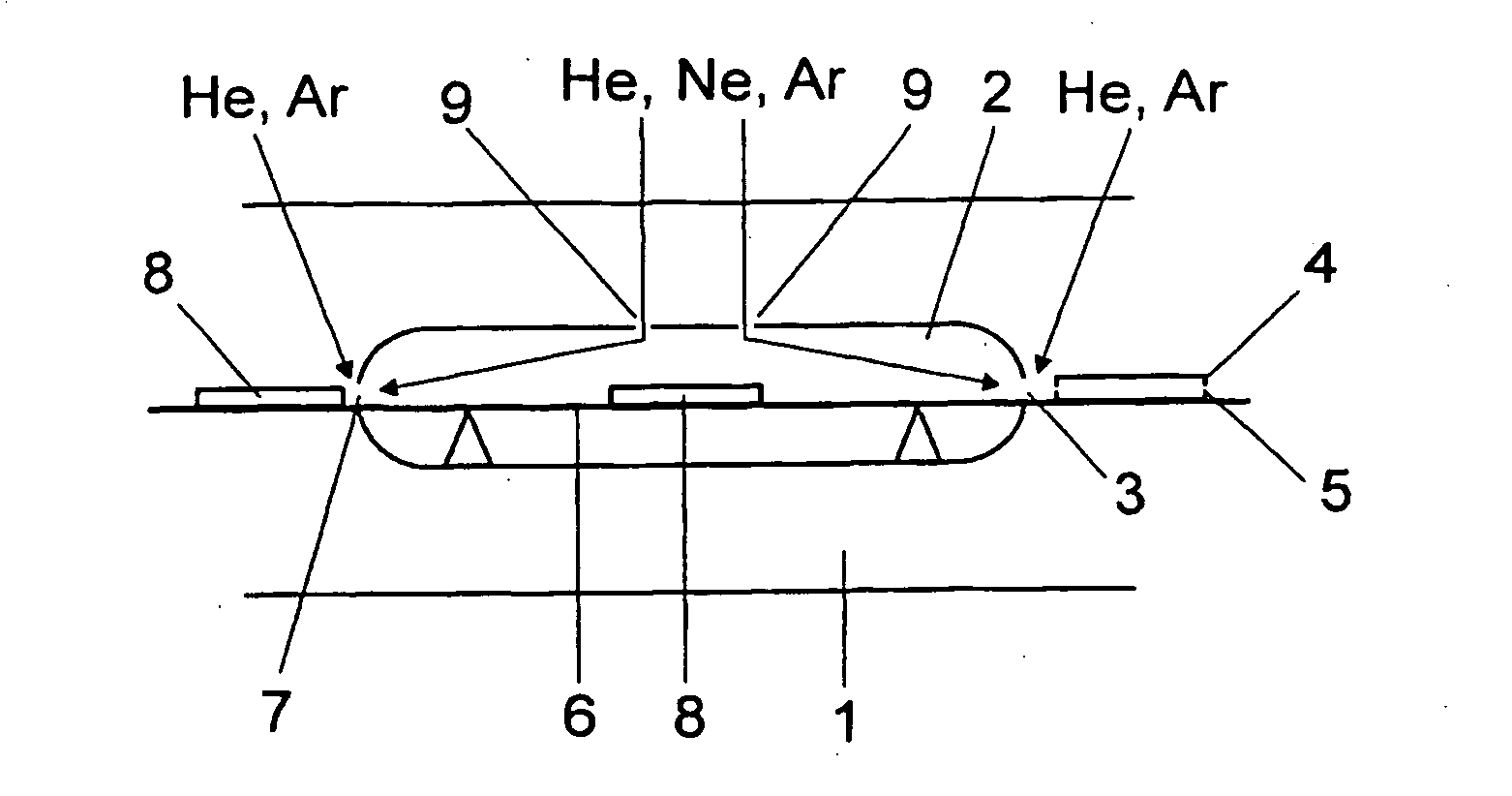
[0036]FIG. 1 shows a continuous furnace 1 for producing dielectric barrier flat radiators. The continuous furnace 1 comprises a tubular hollow body 2 which is approximately 160 times as long as it is high (expressed in terms of the internal dimensions), i.e. it is not represented true to scale. For example, the dimensions of 8 m length, 60 cm width and 5 cm height may be envisaged. It has an opening 3 for introducing discharge vessel parts 4 and 5.

[0037]During operation, the discharge vessel parts 4 and 5 are introduced into the hollow body 2 and moved through it using a conveyor belt 6 known per se. Closed discharge vessels 8 then leave the hollow body 2 through the opening 7 of the hollow body 2. It is thus a “first” hollow body. The total area of the openings 3 and 7 of the hollow body 2 is much less than the total area of the openings (not shown) of the furnace 1.

[0038]A discharge gas is introduced into the hollow body 2 through the gas feeds 9 during operation, and specifically...


PUM


Abstract

The invention relates to a furnace (1) for producing a discharge lamp, comprising an outer furnace wall. It is characterized by a hollow body (2) that surrounds the outer furnace wall and is provided to receive discharge vessel parts (4, 5) and joints of the same to a discharge vessel (8) for the discharge lamp. The hollow body (2) further comprises a discharge gas supply (9) for flooding with a discharge gas such that a discharge vessel (8) provided in the hollow body (2) is filled with the same. The invention further relates to a production method for discharge lamps comprising such a furnace (1).

Description

TECHNICAL FIELD[0001]The present invention relates to a furnace for producing a discharge lamp, and to a method for producing a discharge lamp using such a furnace.PRIOR ART[0002]Discharge lamps have a closed discharge vessel containing a discharge gas. It is known to assemble a plurality of discharge vessel parts to form a discharge vessel in a furnace by supplying heat. It is known in particular to assemble discharge vessel parts in a vacuum furnace under a discharge gas atmosphere.[0003]DE 101 47 727 A1 discloses a continuous furnace for assembling discharge vessel parts to form discharge vessels. In this case the discharge vessel parts are introduced into an atmosphere of the discharge gas and assembled under this atmosphere.SUMMARY OF THE INVENTION[0004]It is an object of the invention to provide a furnace which is advantageous in respect of the production of a discharge lamp, and to provide a corresponding production method.[0005]The invention relates to a furnace for producin...

Claims


Application Information

Patent Timeline
Patent Type & Authority Applications(United States)
IPC IPC(8): H01J9/38
CPCH01J9/268H01J9/38H01J9/395H01J9/40H01J9/48
Inventor HITZSCHKE, LOTHARVOLLKOMMER, FRANK
Owner OSRAM GMBH
Why Eureka
Try Eureka