Composite material engineered from metal and resin and production method thereof

a technology of composite materials and metals, applied in the field of composite materials, can solve the problems of large work processes, small adhesion strength of the anchoring method, and insufficient bonding strength, and achieve the effect of easy and uniform mixing of resins

Inactive Publication Date: 2010-08-05
TOYODA GOSEI CO LTD
View PDF7 Cites 16 Cited by
  • Summary
  • Abstract
  • Description
  • Claims
  • Application Information

AI Technical Summary

Benefits of technology

[0025]It is preferable that an adhesive modifying agent is easily and uniformly mixed in the resin. Such non-limited example of the adhesive modifying agent is a modified graft copolymer. The modified graft copolymer is given by modifying a graft copolymer having a polyethylene, a polystyrene or the like as a main chain and a styrenic polymer as a side chain with the adhesive functional group. Another non-limited exa

Problems solved by technology

However, the bonding method by anchor effect has small adhesion strength.
On the other hand, the bonding method by an adhesive requires an adhesive layer at an interface between the metal and the resin, and therefore requires a lot

Method used


Image

  • Composite material engineered from metal and resin and production method thereof
  • Composite material engineered from metal and resin and production method thereof

Examples


examples

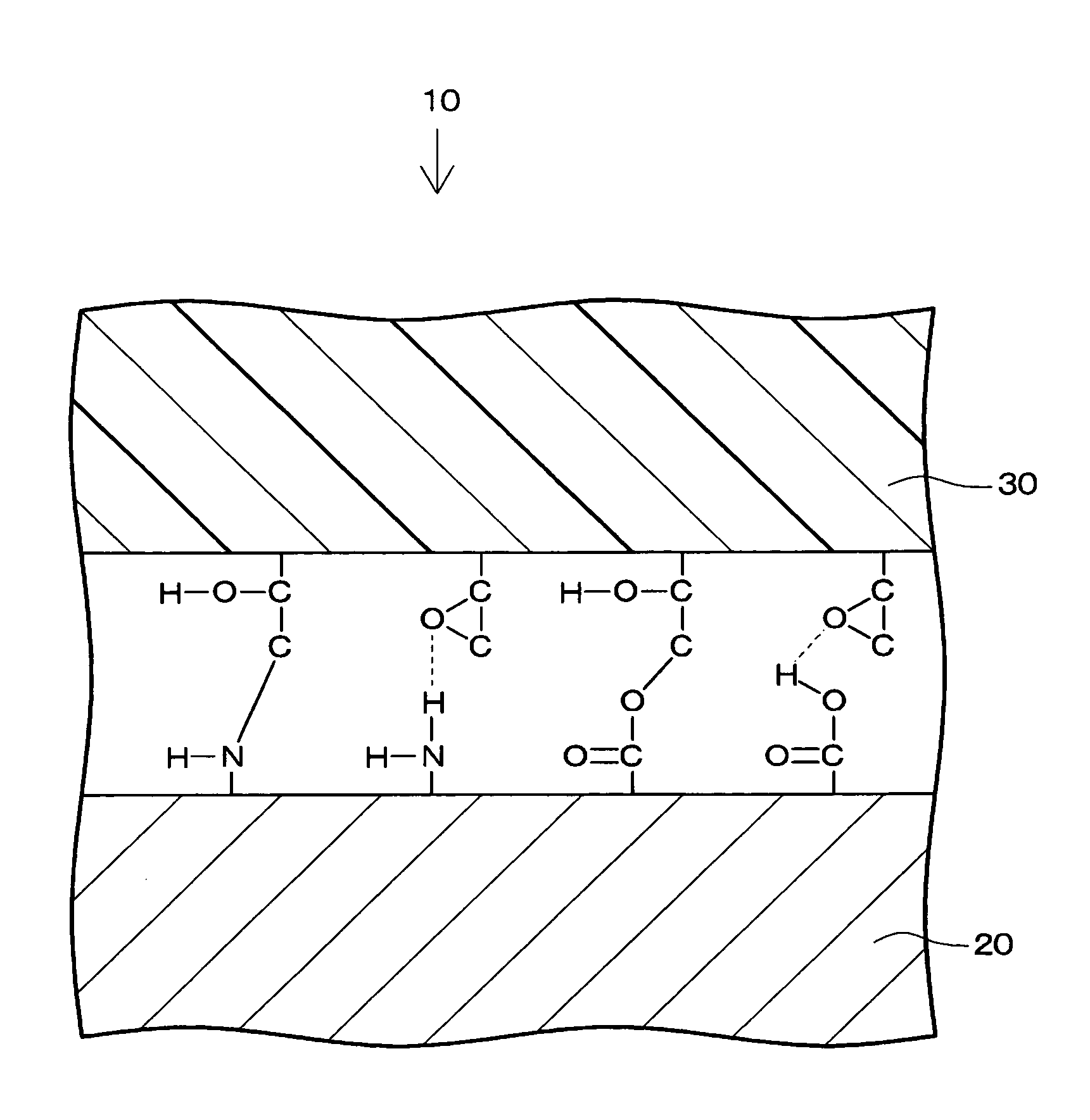
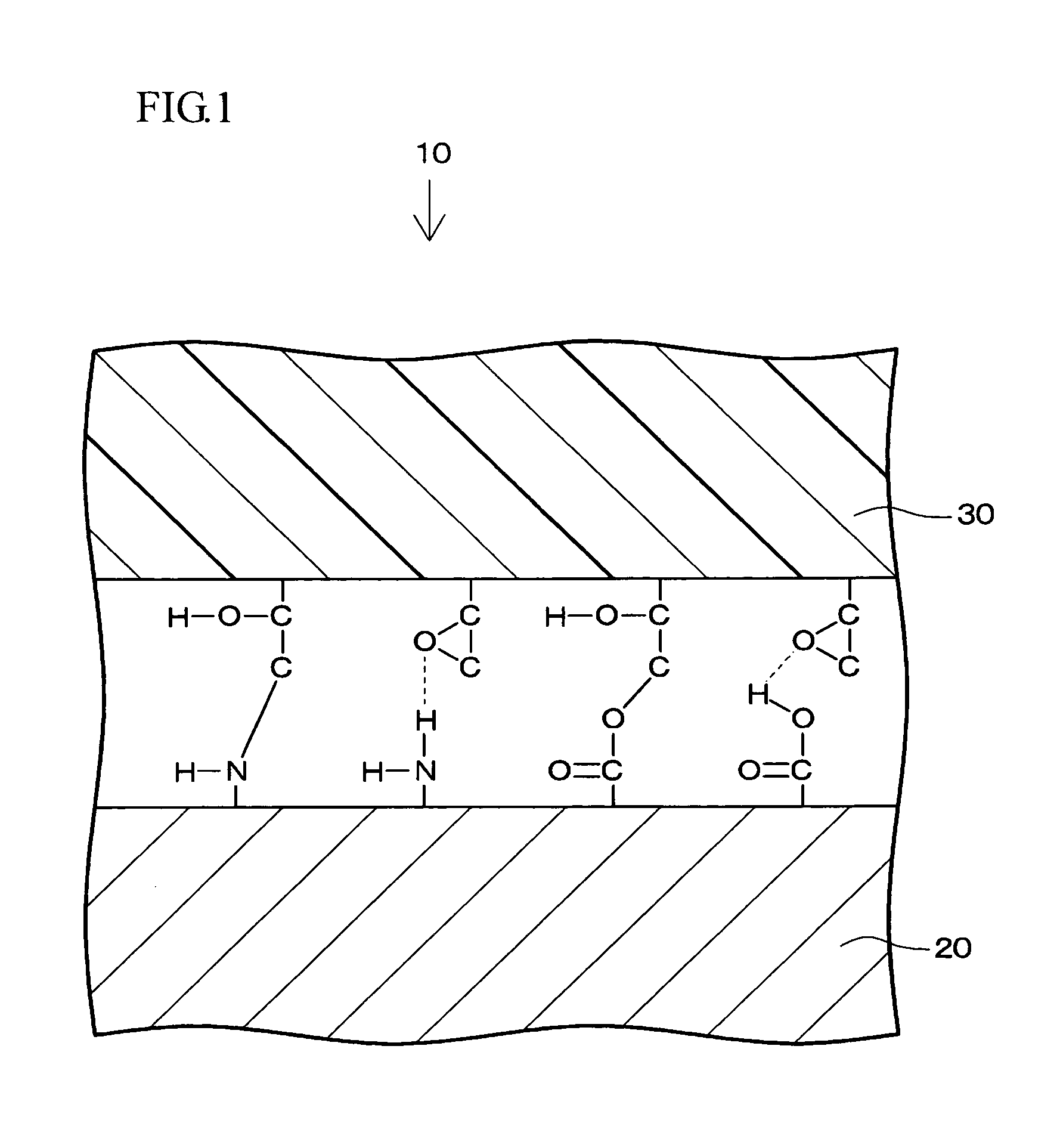
[0036]An example of a composite material engineered from metal and resin according to the present invention is shown in FIG. 1. The composite material 10 has a metal portion 20 composed of metal on which surface at least one of a carboxyl group and an amino group is imparted, and a resin portion 30 in which an adhesion modifying agent including an epoxy group is mixed. The metal portion 20 and the resin portion 30 are bonded by a chemical bond at an interface between the metal portion 20 and the resin portion 30. The chemical bond is the one between the epoxy and at least one of the carboxyl group and the amino group.

[0037]Twenty five (25) examples of the present invention in each of which aluminum (A1050) was used for the metal portion were prepared and the adhesion strength thereof was evaluated. Another 15 comparative examples in each of which aluminum was used for the metal portion were prepared and the adhesion strength thereof was also evaluated.

[0038]The evaluation result of ...

second examples

[0059]The adhesion strength of the second examples and the second comparative examples which are same as above 25 examples and 15 comparative examples except for that the metal portion is not composed of aluminum (A1050) but of copper (C1100) is evaluated. The second examples and the second comparative examples were prepared by same manner as the above described examples and comparative examples.

[0060]The evaluation results of the adhesion strength of the second examples are shown in Table 3, and that of the second comparative examples are shown in Table 4. Further, the kind of the resin used in the resin portions of the second examples and the second comparative examples and the amount of adhesive modifying agent mixed in the resin for the second examples and the second comparative examples are also shown in Tables 3 and 4. Furthermore, compounds used for the surface treatment of the metal portions of the second examples and the second comparative examples are also shown in Tables ...


PUM

PropertyMeasurementUnit
Percent by massaaaaaaaaaa

Abstract

A composite material engineered from metal and resin and a production method of the composite material. The composite material includes a metal portion composed of metal; a resin portion composed of resin; a polar functional group imparted to a surface of the metal portion; and an adhesion modifying agent mixed in the resin and including an adhesive functional group which interacts with the polar functional group. The metal portion and the resin portion are bonded by the interaction between the polar functional group and the adhesive functional group.

Description

CROSS REFERENCE TO RELATED APPLICATIONS[0001]The present application claims priority from Japanese patent application No. 2009-021017 filed on Jan. 30, 2009, and the entire subject matter of which is incorporated herein by reference.TECHNICAL FIELD[0002]The present invention relates to a composite material in which a metal portion composed of metal is bonded to a resin portion composed of resin, and a production method thereof.BRIEF DESCRIPTION OF RELATED ART[0003]Recently, various composite materials are developed. Such composite materials are engineered from bonded different materials and utilize the characteristics of the bonded materials. Especially, since metal and resin have characteristics distinct from each other, the composite materials engineered from metal and resin have unprecedented characteristics. Accordingly, it is expected that their use will further increase in the future.[0004]For a method of bonding metal and resin in a composite material engineered from metal an...

Claims


Application Information

Patent Timeline
IPC IPC(8): C08G79/00
CPCB29C45/14311B29C45/14778C09J181/02C09J135/06C08L81/02C08L33/10C08L23/30C08L23/0838C08J5/128B32B15/08B32B7/10B29C66/71B29K2705/00B29L2009/003C08L2666/04C08L2666/14C08L2666/02B29C65/00B32B5/142B32B15/20B32B27/18B32B27/20B32B27/286B32B27/302B32B27/304B32B27/32B32B27/34B32B27/36B32B2262/101B32B2307/50B32B2410/00B32B2419/00B32B2437/00B32B2457/00B32B2553/00B32B2581/00B32B2605/00Y10T428/31529Y10T428/31533Y10T428/31536Y10T428/31699Y10T428/31725Y10T428/31786
Inventor IMAI, HIDEYUKINAGAMORI, YOSHINORITAKEDA, SHINICHI
Owner TOYODA GOSEI CO LTD
Why Eureka
Try Eureka