Ultrasonic drying system and method

a technology of ultrasonic drying and ultrasound, which is applied in the direction of drying machines, lighting and heating apparatus, furnaces, etc., can solve the problems of large/space-consuming, costly, and difficult to operate the combustion equipment of the pulse, and achieve the effect of reducing heat loss

Active Publication Date: 2010-08-12
HEAT TECH
View PDF24 Cites 44 Cited by
  • Summary
  • Abstract
  • Description
  • Claims
  • Application Information

AI Technical Summary

Benefits of technology

[0008]In another aspect of the invention, the ultrasonic transducers are positioned a spaced distance from the material to be dried of about (λ)(n/4), where λ is the wavelength of the ultrasonic oscillations and “n” is plus or minus 0.5 of an odd integer (0.5 to 1.5, 2.5 to 3.5, 4.5 to 5.5, etc.). Preferably, the ultrasonic transducers are positioned relative to the material to be dried the spaced distance of about (λ)(n/4), where “n” is an odd integer (1, 3, 5, 7, etc.). In this way, the amplitude of the acoustic oscillations is at about maximum at the interface surface of the material to mo

Problems solved by technology

Thus, this approach has provided significant improvement in heat-transfer rates, but the pulse combustion equipment is large/space-consuming and costly to purchase and operate.
Additionally, a variety of industries require more compact e

Method used


Image

  • Ultrasonic drying system and method
  • Ultrasonic drying system and method
  • Ultrasonic drying system and method

Examples


Embodiment Construction

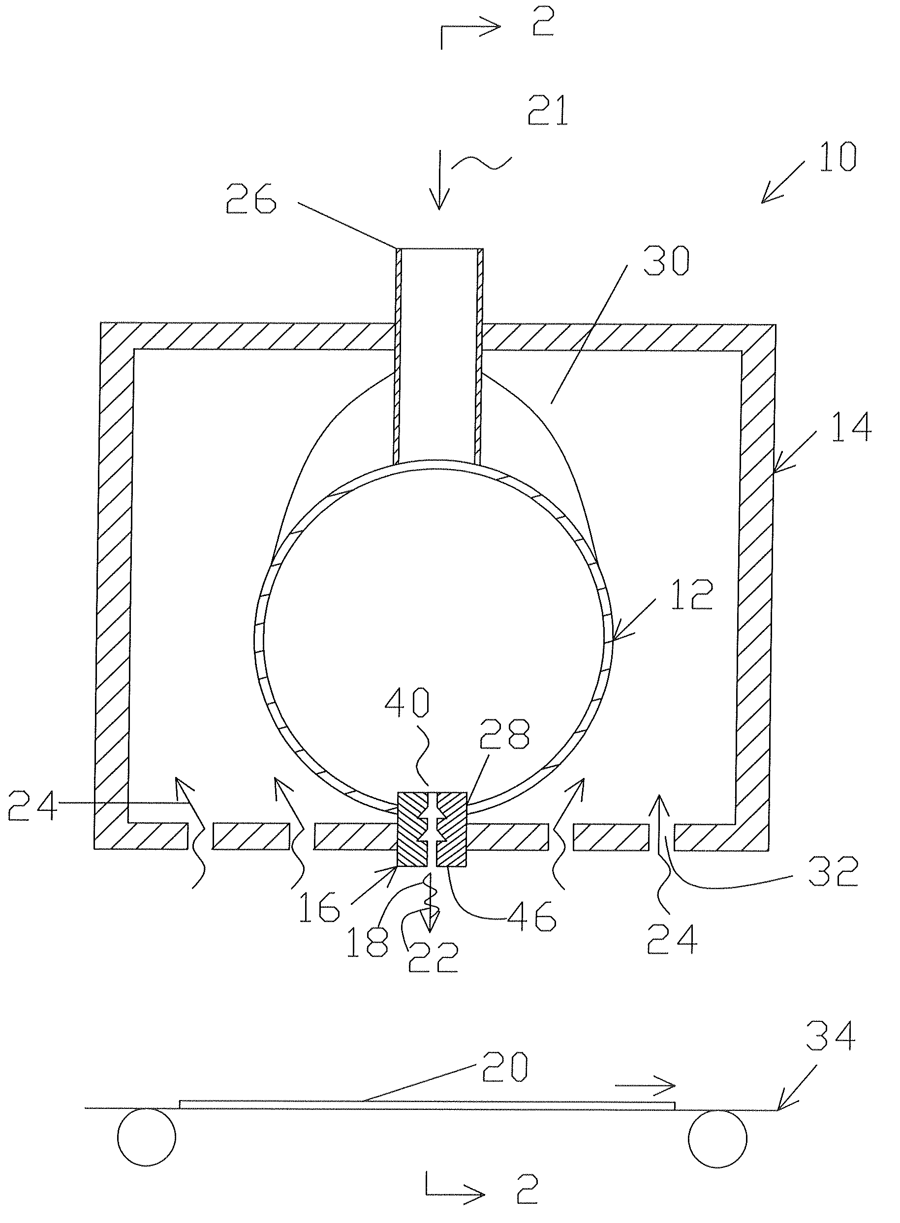
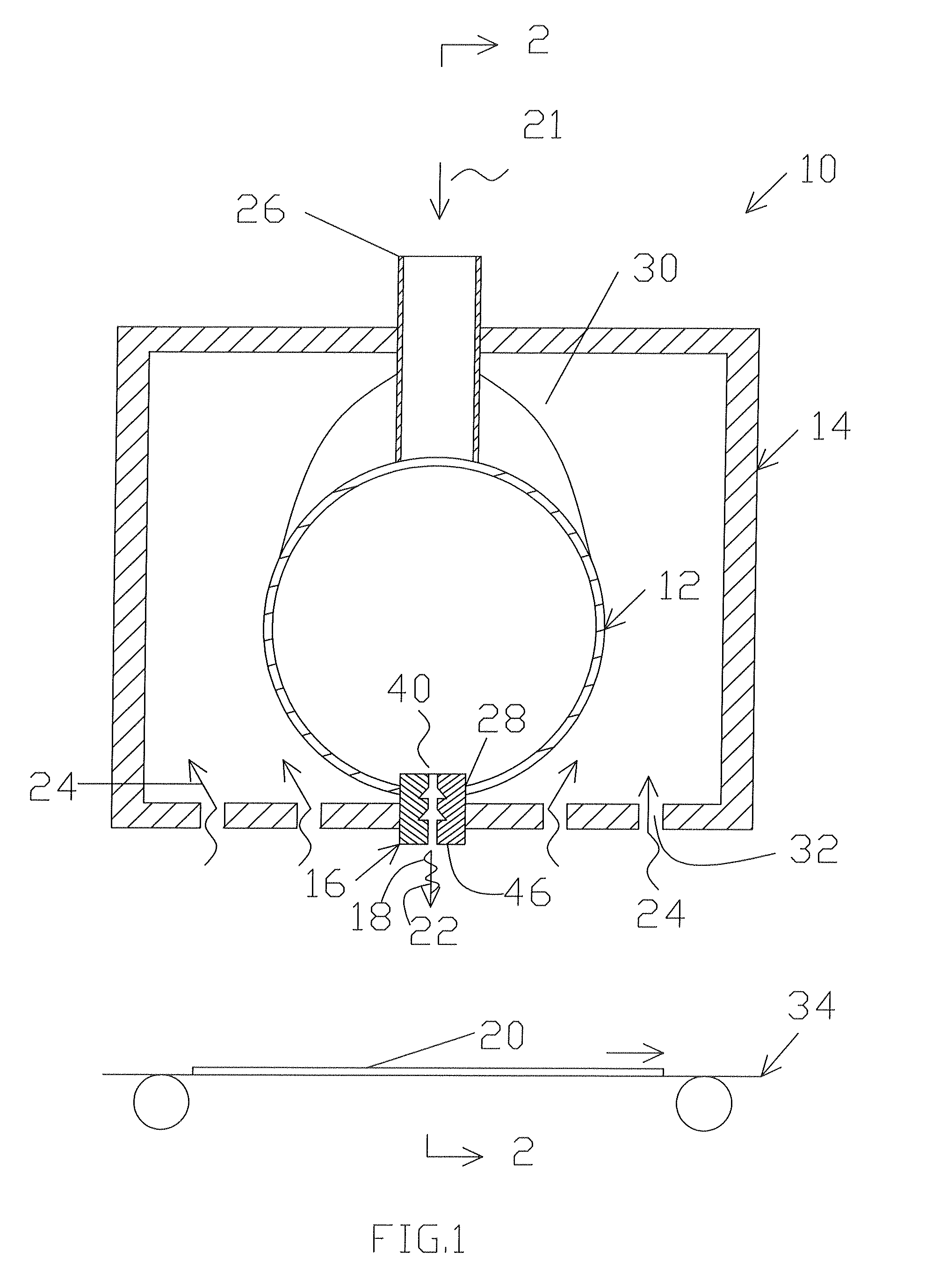
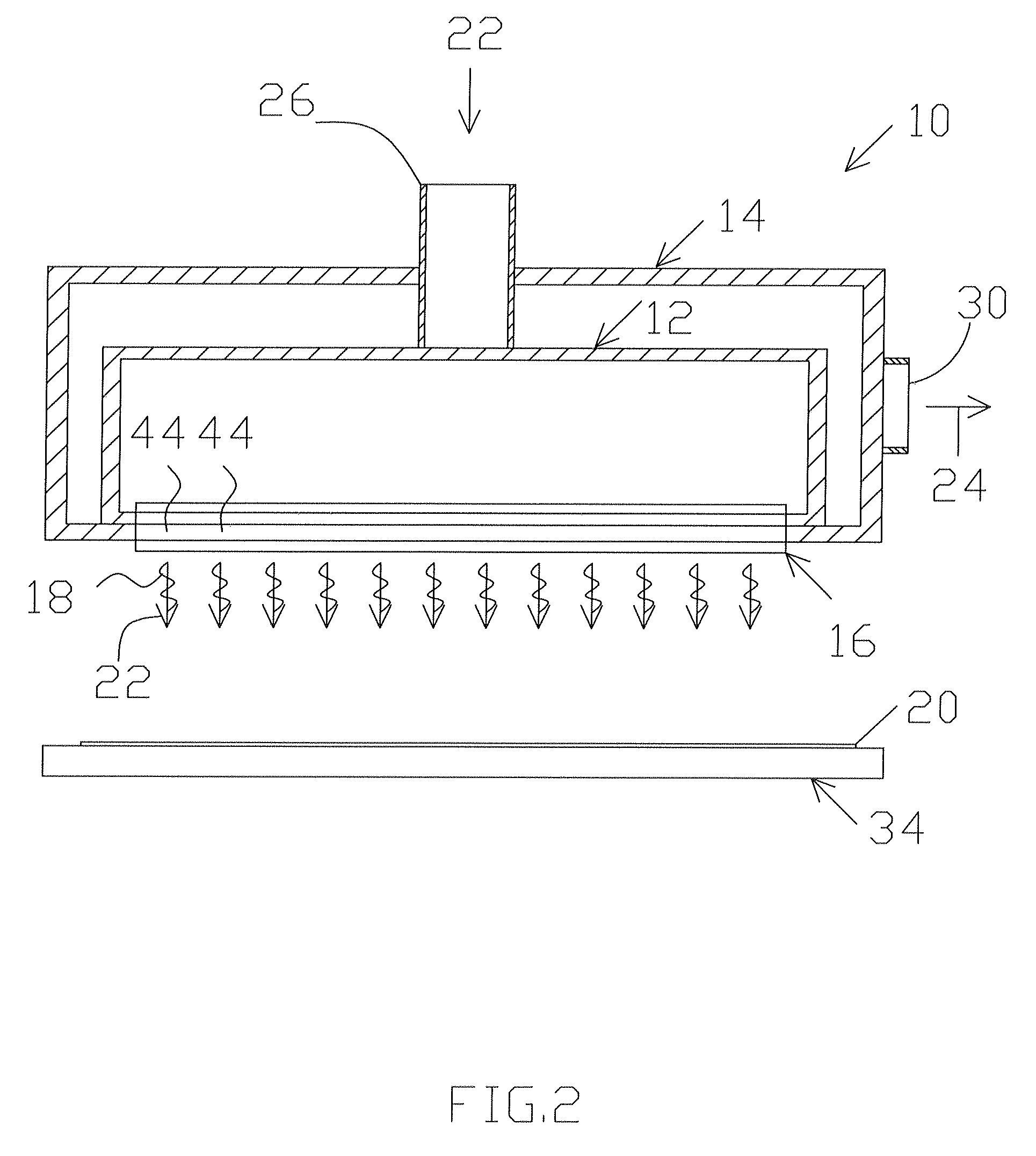
[0049]The present invention provides drying systems and methods that include the use of ultrasound to more effectively break down the boundary layer and thereby increase the heat and / or mass transfer rate. Example embodiments of the invention are described herein in general configurations for illustration purposes. The invention also provides specific configurations for use in specific applications such as but not limited to printing, residential and commercial cooking appliances, food processing equipment, textiles, carpets, converting industries, fabric dyeing, and so on. In particular, the invention can be configured for flexographic and gravure printing of wallpaper, gift-wrap paper, corrugated containers, folding cartons, paper sacks, plastic bags, milk and beverage cartons, candy and food wrappers, disposable cups, labels, adhesive tapes, envelopes, newspapers, magazines, greeting cards, and advertising pieces. The invention can be adapted for these and many other batch and co...


PUM


Abstract

A drying apparatus and method including heated airflow and ultrasonic transducers. The ultrasonic transducers are arranged and operated for effectively breaking down the boundary layer to increase the heat transfer rate. The ultrasonic transducers are spaced from the material to be dried a distance of about (λ)(n/4), where λ is the wavelength of the ultrasonic oscillations and n is an odd integer (i.e., 1, 3, 5, 7, etc.). In this way, the amplitude of the ultrasonic oscillations is maximized to more-effectively agitate the boundary layer. In addition, the ultrasonic transducers are operated to produce about 120-190 dB (preferably, about 160-185 dB) at the interface surface of the material to be dried. In one embodiment, the ultrasonic transducers are of a pneumatic type. In another embodiment, the ultrasonic transducers are of an electric type. And in other embodiments, infrared and/or UV light devices are included for further boundary layer disruption.

Description

TECHNICAL FIELD[0001]The present invention relates generally to heating and drying technologies and, in particular, to heating and drying assisted with ultrasound.BACKGROUND OF THE INVENTION[0002]It is well known that the majority of energy intensive processes are driven by the rates of the heat and mass transfer. Specific details of a particular application, such as the chemistry of a substrate to be dried (e.g., a factor in label printing, sheet-fed and continuous printing, converting, packaging, mass mailing), the temperature of a material being applied, the needed residence time for a coating to dry, and water or solvent evaporation rates, are necessary for a drying and heating process to work properly. These factors dictate the size of the drying equipment.[0003]It is also well known that the main thing that prevents an increase in heating and drying rates is the boundary layer that is formed around the subject or material to be heated or dried. In modern heating and drying pra...

Claims


Application Information

Patent Timeline
IPC IPC(8): F26B7/00F26B3/04F26B5/02
CPCF26B3/283F26B5/02B41F23/0466F26B21/004F26B7/00
Inventor PLAVNIK, ZINOVY
Owner HEAT TECH
Why Eureka
Try Eureka