
Device and method for recirculating exhaust gas in an internal combustion engine

a technology of internal combustion engine and exhaust gas, which is applied in the direction of machines/engines, indirect heat exchangers, lighting and heating apparatus, etc., can solve the problems of reducing the temperature of exhaust gas, affecting the reliability of the exhaust gas treatment component, and affecting the efficiency of the internal combustion engine, so as to achieve a high rate of exhaust gas recirculation. , the effect of easy operation

Inactive Publication Date: 2010-08-12
BEHR GMBH & CO KG
View PDF11 Cites 5 Cited by
  • Summary
  • Abstract
  • Description
  • Claims
  • Application Information

AI Technical Summary

Benefits of technology

[0006]It is therefore an object of the invention to provide a device and a method for recirculating exhaust gas, which easily achieves a high rate of exhaust gas recirculation.
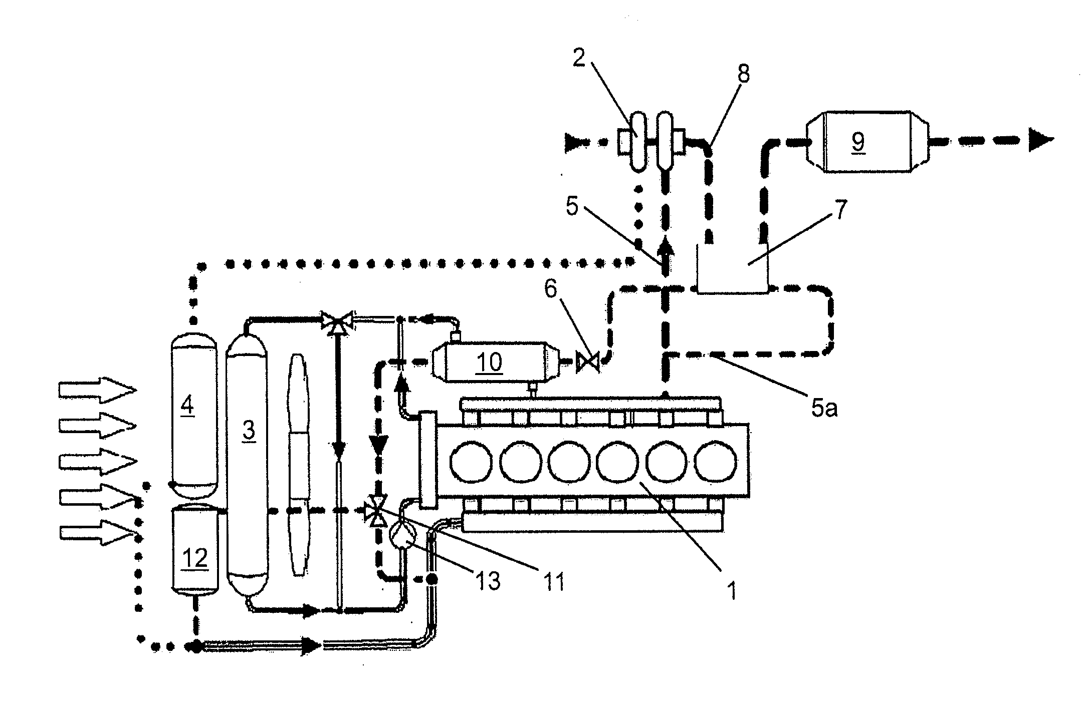
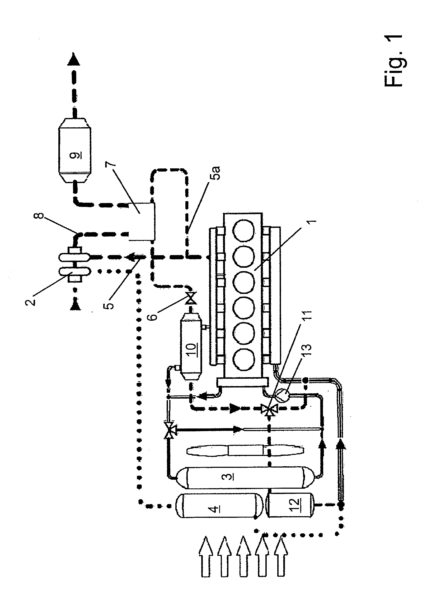
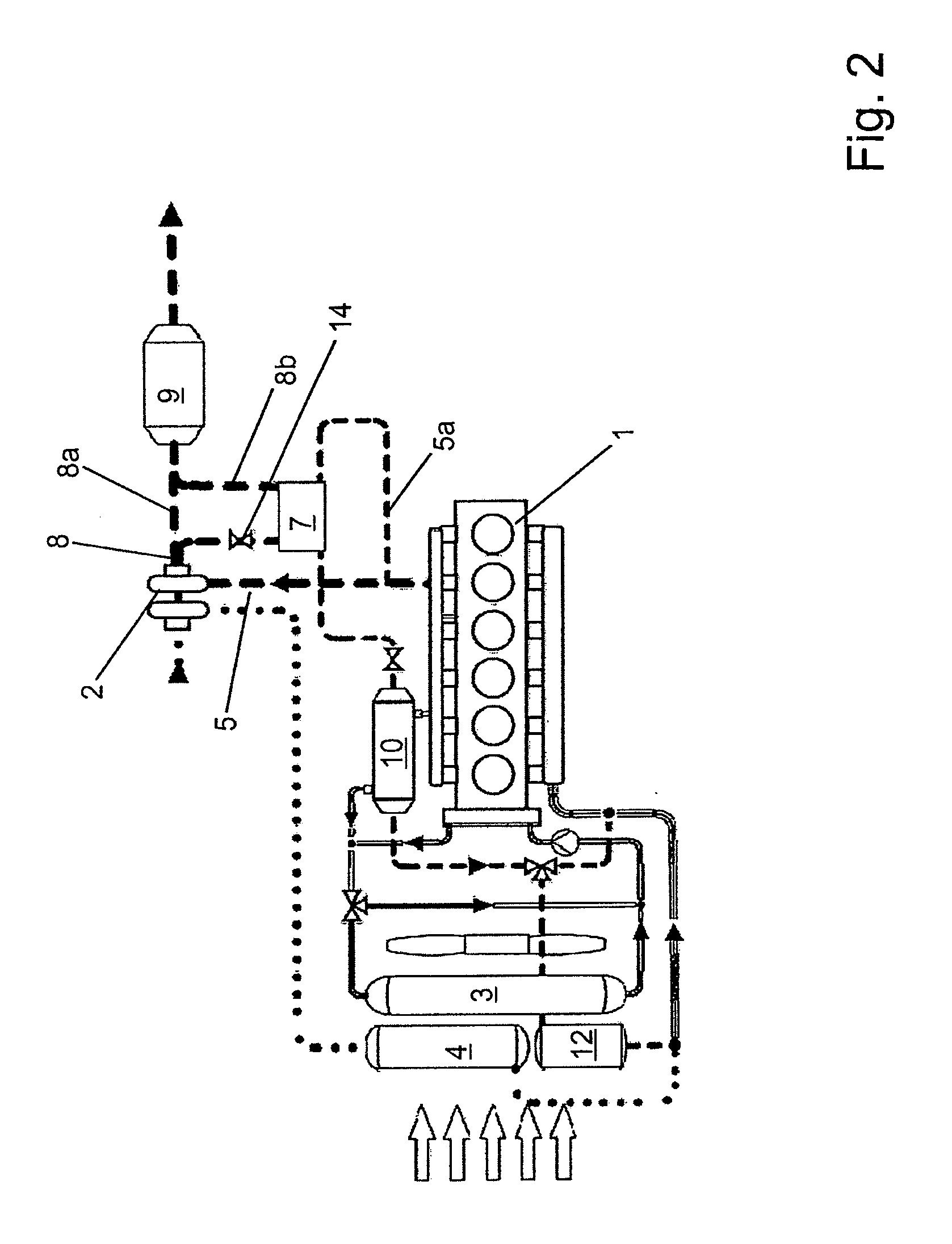
[0007]The exhaust gas temperature on a low pressure side of a compressor regularly lies below a temperature on a high pressure side so that, according to an embodiment of the invention, a portion of the heat of the branched-off exhaust gas flow to be recirculated on the high pressure side may be transferred to the exhaust gas flow on the low pressure side with the aid of a heat transfer apparatus. The required cooling capacity of the exhaust gas cooler is reduced thereby, and the recirculation rate may be increased, using an existing exhaust gas cooler. In particular, recirculation rates of more than 30%, particularly advantageously recirculation rates of more than 35% and particularly advantageously recirculation rates of 40% or more than 40% are achievable in practice without making major changes to existing exhaust gas coolers.

Problems solved by technology

Since the conventional recirculation of exhaust gas may also result in a reduction in exhaust gas temperature downstream from the compressor, the reliable functionality of the exhaust gas treatment component may, under some circumstances, be jeopardized if the recirculation rate is further increased.

Method used


Image

  • Device and method for recirculating exhaust gas in an internal combustion engine
  • Device and method for recirculating exhaust gas in an internal combustion engine
  • Device and method for recirculating exhaust gas in an internal combustion engine

Examples


Embodiment Construction

[0022]The exemplary embodiment of the invention according to FIG. 1 comprises an internal combustion engine 1, which in the present case is a supercharged diesel engine of a commercial vehicle. The exhaust gas of engine 1 flows under high pressure and at high temperature in a line 5 to a compressor designed as an exhaust gas turbocharger for the purpose of compressing charge air which is cooled in a direct, i.e. air-circulated, charge air cooler 4 situated at the front of the vehicle upstream from an engine coolant radiator 3.

[0023]Line 5 on the high pressure side has a branch from which an exhaust gas flow 5a branches for recirculation to internal combustion engine 1. The volume of the branched-off exhaust gas may be regulated via a valve 6 situated in the branch line.

[0024]According to an embodiment of the invention, the exhaust gas flow which has been branched off for recirculation first flows through a heat transfer apparatus 7, which in the first exemplary embodiment is designe...


PUM


Abstract

An apparatus for returning exhaust gas of an internal combustion engine is provided. The apparatus includes a compressor that is driven by exhaust gas, wherein an exhaust-gas flow enters into the compressor on a high-pressure side and exits the compressor on a low-pressure side. A branch is provided on the high-pressure side with regard to the compressor for returned exhaust gas, and at least one exhaust-gas cooler is provided for transferring heat out of the branched-off exhaust-gas flow into a cooling medium. A heat exchanger is provided, via which heat can be transferred between the exhaust-gas flow, which branches off on the high-pressure side, and an exhaust-gas flow on the low-pressure side with regard to the compressor.

Description

[0001]This nonprovisional application is a continuation of International Application No. PCT / EP2008 / 008888, which was filed on Oct. 21, 2008, and which claims priority to German Patent Application No. 10 2007 051 659.4, which was filed in Germany on Oct. 26, 2007, and which are both herein incorporated by reference.BACKGROUND OF THE INVENTION[0002]1. Field of the Invention[0003]The invention relates to a device for recirculating exhaust gas in an internal combustion engine and to a method for recirculating exhaust gas in an internal combustion engine.[0004]2. Description of the Background Art[0005]A method is known for branching off exhaust gas in an internal combustion engine and resupplying it as an admixture after cooling. Among other things, reductions in harmful substances such as nitrogen oxides are achieved thereby. One of the effects responsible for this is the reduction of the engine peak temperature, in particular in diesel engines. At present, recirculation rates of 30% a...

Claims


Application Information

Patent Timeline
Patent Type & Authority Applications(United States)
IPC IPC(8): F02B29/04
CPCF01N3/021F01N3/20F01N5/02F02B37/00F02M25/0707F02M25/0718Y02T10/16F02M25/0731F02M25/0732F02M25/0796F28D15/02F28D21/0003Y02T10/121F02M25/073F02M26/05F02M26/15F02M26/27F02M26/28F02M26/24F02M26/71Y02T10/12
Inventor OBERLECHNER, CHRISTIANPFISTER, FLORIANPANTOW, EBERHARD
Owner BEHR GMBH & CO KG
Learn More