Method and apparatus for noise reduction in ultrasound detection

a technology of ultrasound detection and noise reduction, applied in the field of ultrasonic sensors, can solve the problems of difficult machine and package to small dimensions, difficult to construct piezoelectric sensors with a relatively small profile, and very small electric voltage of piezoelectric signal,

Active Publication Date: 2010-08-12
TOTAL WIRE CORP
View PDF30 Cites 32 Cited by
  • Summary
  • Abstract
  • Description
  • Claims
  • Application Information

AI Technical Summary

Benefits of technology

[0007]One aspect provides an ultrasonic sensor. In one embodiment, the sensor includes: (1) an optical interferometer having an input and two outputs, (2) a polarization-maintaining probing fiber having a reflective coating at a distal end thereof, (3) a polarization modulator coupled between the input and a proximal end of the probing fiber and (4) a photodetector coupled to the two outputs and configured to derive an electronic signal that varies based on an ultrasonic signal received at the distal end.

Problems solved by technology

PZT is a ceramic polycrystal with an inherent grain size that makes it difficult to machine and package to small dimensions unless it is attached to a larger substrate.
Furthermore, the piezoelectric signal is a very small electric voltage that is subject to transmission line loss and electromagnetic interference.
The need to shield and pre-amplify signals makes it hard to construct piezoelectric sensors with a relatively small profile.
However, these devices are costly to make, and reliability issues are associated with the need to forward-bias the sensing capacitors.
For this sensor to function properly, the thickness of the polymer constituting the etalon must be controlled to a very high precision during fabrication, which is difficult to do.
Furthermore, changes in application environment such as temperature and pressure can significantly alter the properties of the etalon and negatively impact sensor performance.
In addition, the fiber optic sensor typically exhibits undesirable ringing or reverberations due to the structure of the sensor that distorts the frequency response.
Such reverberations are also problematic in IVUS applications, because it degrades longitudinal image resolution, and it causes a large amount of so-called “ringdown” effect that makes it difficult to image objects close to the surface of IVUS catheter.

Method used


Image

  • Method and apparatus for noise reduction in ultrasound detection
  • Method and apparatus for noise reduction in ultrasound detection
  • Method and apparatus for noise reduction in ultrasound detection

Examples


Embodiment Construction

[0019]Described herein are various embodiments of a method and apparatus for noise reduction in ultrasound detection. Those skilled in the art should understand, however, that the invention in its broadest form may be embodied in ways that this Detailed Description may not set forth. Therefore, specific details disclosed herein are not to be interpreted as limiting, but rather as a basis for the claims and as a representative basis for teaching one skilled in the art to employ the invention in virtually any system, structure or manner.

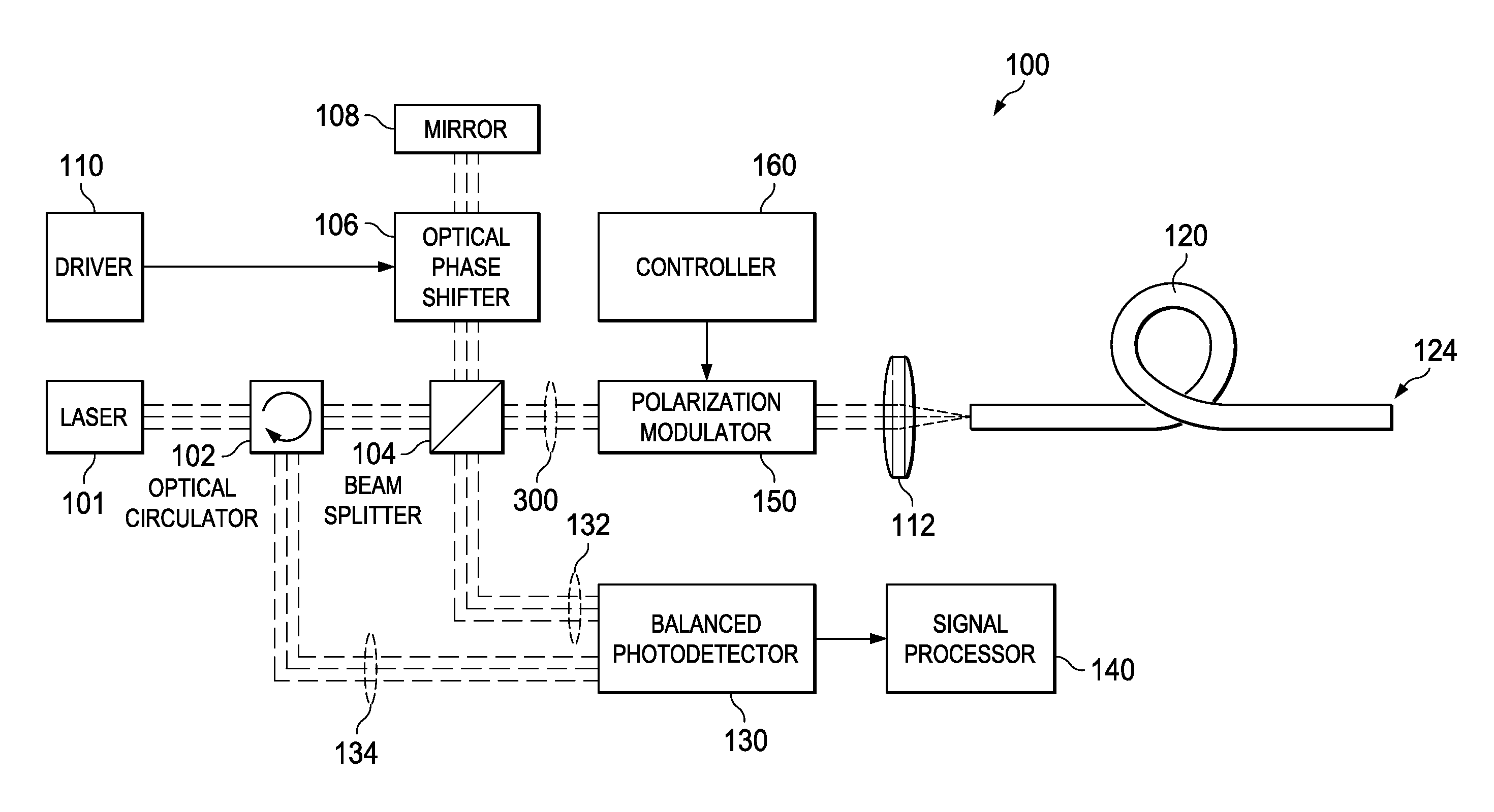
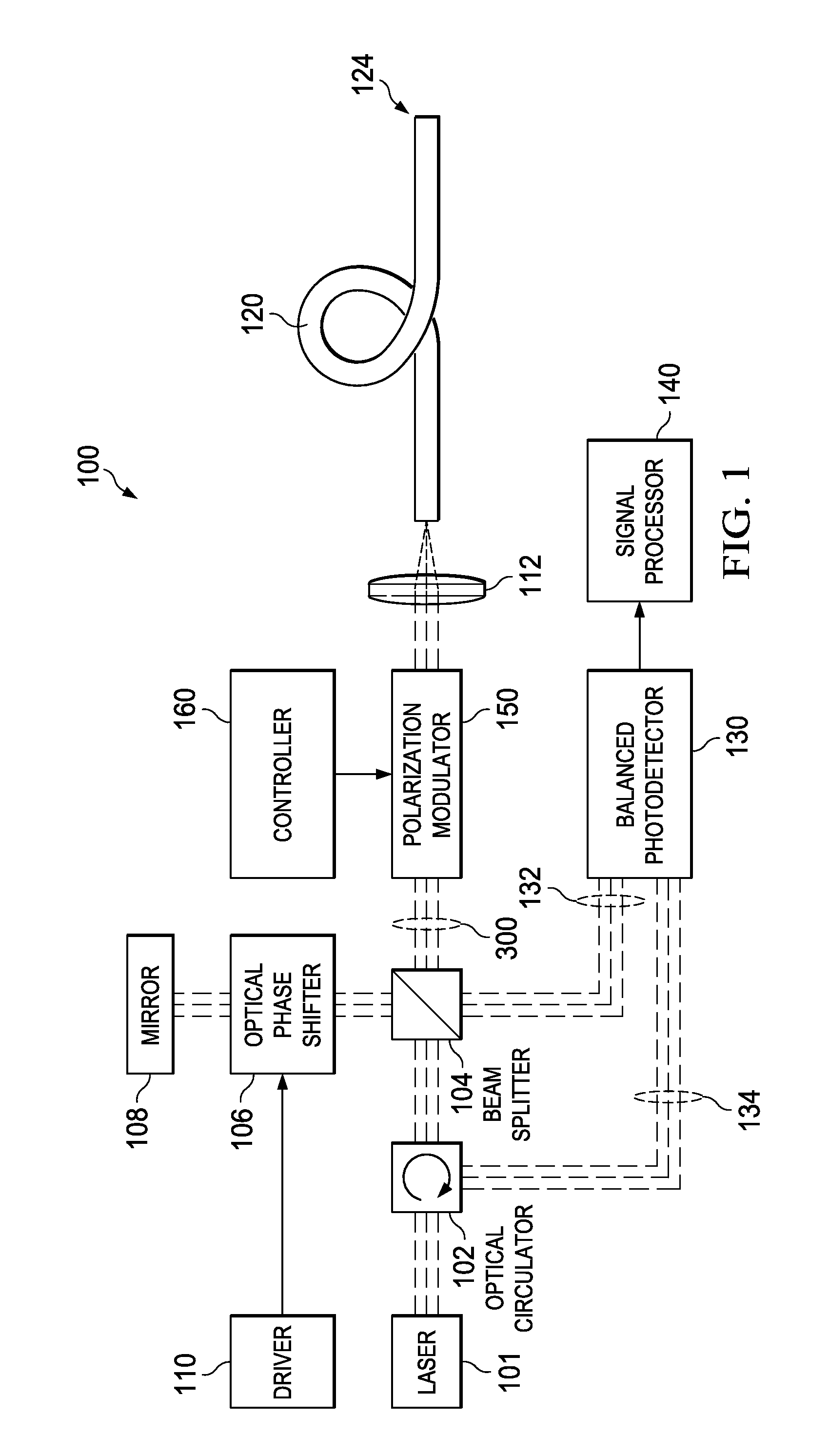
[0020]FIG. 1 illustrates a schematic view of one embodiment of an ultrasound sensor 100 constructed according to the principles of the invention. The ultrasound sensor 100 employs the structure of a Michelson interferometer. Coherent (e.g., laser) light from a laser 101 provides the input to the interferometer. The light passes through an optical circulator 102, a beamsplitter 104, a polarization modulator 150, a focusing lens 112, and couples into a p...


PUM


Abstract

Method and apparatus for noise reduction in ultrasound detection with the steps of: an optical interferometer having a reference arm and a signal arm that includes a polarization-maintaining probing fiber having a reflective coating at a distal end, a way to couple the probing fiber to ultrasound, a way to generate two output beams from the interferometer, a device to modulate the polarization state of the light in the probing fiber, and a detection mechanism responsive to the ultrasonic signals at the distal tip of the probing fiber.

Description

CROSS-REFERENCE TO RELATED APPLICATION[0001]This application is a continuation-in-part of U.S. application Ser. No. 11 / 927,889, filed by Zhou on Oct. 30, 2007, entitled “Ultrasonic Pressure Sensor and Method of Operating the Same.” This application also claims the benefit of U.S. Provisional Application Ser. No. 61 / 240,994, filed by Zhou on Sep. 9, 2009, entitled “Method and Apparatus for Noise Reduction in Ultrasound Detection,” and U.S. Provisional Application Ser. No. 61 / 254,560, filed by Zhou on Oct. 23, 2009, entitled “Method and Apparatus for Noise Reduction in Ultrasound Detection.” All of these applications are commonly assigned with this application and incorporated herein by reference.TECHNICAL FIELD[0002]This application is directed, in general, to ultrasound sensors and, more specifically, to a method and apparatus for noise reduction in ultrasound detection.BACKGROUND[0003]An ultrasonic pressure sensor measures ultrasonic pressure and converts it into an electric voltag...

Claims


Application Information

Patent Timeline
Patent Type & Authority Applications(United States)
IPC IPC(8): G01H9/00G01B9/02
CPCG01H9/004G01H9/006G01S7/4818G01S7/499G01S17/88G01S15/8968
Inventor ZHOU, GAN
Owner TOTAL WIRE CORP
Why Eureka
Try Eureka