Hydraulic system having an adjustable hydrostatic machine

a hydrostatic machine and hydrostatic system technology, which is applied in the direction of machines/engines, positive displacement liquid engines, pump parameters, etc., can solve the problem of inability to centralize the adjusting piston, and achieve the effect of reducing the adjusting pressure, preventing the intake problem, and simplifying the mechanical coupling

Inactive Publication Date: 2010-08-12
ROBERT BOSCH GMBH
View PDF3 Cites 22 Cited by
  • Summary
  • Abstract
  • Description
  • Claims
  • Application Information

AI Technical Summary

Benefits of technology

[0017]It is also advantageous that, in the event of a disappearing control force and a balance of forces between the counter-force and the force onto the regulating element which is dependent upon the position of the adjusting piston, the hydrostatic machine is adjusted to a non-zero delivery volume. This type of adjustment in the rest position of the hydrostatic system to a non-zero delivery volume ensures that after initial operation and in the event of a disappearing control signal a minimum delivery volume is already delivered by the hydrostatic machine. By reason of this minimal delivery volume, a slightly increased pressure already exists in the hydraulic system and can be used in order to actuate the adjusting device of the hydrostatic machine. The said adjustment in the rest position also prevents intake problems from occurring in the hydrostatic machine by reason of an incorrect pivot side.
[0018]In addition to the adjusting piston which influences the hydrostatic machine with an adjusting force starting from a rest position in the direction of a first end position, the adjusting device preferably comprises a further adjusting piston which is also referred to as a counter-piston and which influences the hydrostatic machine with an adjusting force in an opposite direction starting from the rest position in the direction of a second end position. This type of division of the adjusting device into a first adjusting piston for a first movement direction and a second adjusting piston for a second movement direction has the advantage that the available installation space can be utilised in a particularly efficient manner in e.g. a hydrostatic axial piston machine. Therefore, it is possible to dispose the two adjusting pistons and the adjusting cylinders, in which the adjusting pistons are disposed, on opposite sides of a pivot cradle or swash-plate. By virtue of the respective adjusting piston, only compressive forces are transmitted to the pivot cradle, which simplifies the mechanical coupling between the adjusting piston and the hydrostatic machine.
[0019]The adjusting pressure chamber delimited by the piston surface of the adjusting piston can preferably be connected to an adjusting pressure source via the regulating valve. In particular, the adjusting pressure source is connected to the regulating valve via a connection line, in which a pressure-reducing valve is disposed. The connection line having the pressure-reducing valve provided therein has the advantage that by means of the pressure-reducing valve an input pressure which is reduced with respect to the working pressure is generated. Therefore, the adjusting pressure source used can be a pressure which is dependent e.g. upon different operating situations of the hydrostatic system. In particular, the delivery pressure of the hydrostatic machine can be provided as an adjusting pressure source. Furthermore, it is particularly advantageous when using the pressure-reducing valve in the connection line to produce the adjusting device by means of a first adjusting piston and a second adjusting piston. The second adjusting piston has a piston surface which is smaller in comparison with the first adjusting piston and is influenced directly by the working pressure of the hydrostatic machine. Reducing the adjusting pressure gained from the working pressure of the hydrostatic machine whilst at the same time having a larger piston surface of the first adjusting piston ensures that the adjusting mechanism of the hydrostatic machine is hydraulically clamped at each point in time. Nevertheless, the maximum possible adjusting pressures of the first adjusting piston are reduced with respect to the actual working pressure. In particular, the actuating means, but also the regulating valve, are thereby subjected only to a smaller pressure loading.
[0020]The adjusting pressure source is preferably a working line of the hydrostatic machine or a further pressure medium source. The working line or the pressure medium source are connected to the connection line via a shuttle valve. The ability to also provide as an alternative a further pressure medium source as an adjusting pressure source in addition to the working line has the advantage that even in the event of a disappearing working line pressure an adjusting pressure sufficient to actuate the hydrostatic system is available. This is particularly advantageous if the hydrostatic system is used in the recovery of kinetic energy by the storage of energy in a hydrostatic accumulator. During operation the hydrostatic accumulator can be completely emptied. In this case, the further pressure medium source can be used to generate a sufficient adjusting pressure in the first adjusting pressure chamber, by means of which the hydrostatic machine can be adjusted to a higher delivery volume during subsequent energy storage.
[0021]The regulating valve can be designed as a 3 / 3-port directional control valve. The use of a 3 / 3-port directional control valve renders it possible to provide in addition a neutral position of the regulating valve between the two end positions. This neutral position is determined by a defined regulating valve position. In this neutral position of the regulating valve, the adjusting pressure chamber delimited by the adjusting piston surface of the first adjusting piston can be connected in a restricted manner to a tank volume and is connected in a restricted manner to the adjusting pressure source.

Problems solved by technology

Although the proposed hydrostatic system permits convenient integration into a pump unit by reason of the arrangement of the feedback spring on the one hand and the proportional magnet on the other hand, it is, however, disadvantageous that a central position of the adjusting piston is not possible in the event of a disappearing control signal and a hydrostatic machine which can be adjusted in two opposite directions can only be moved to its neutral position by the generation of a control force by the proportional magnet.

Method used


Image

  • Hydraulic system having an adjustable hydrostatic machine
  • Hydraulic system having an adjustable hydrostatic machine
  • Hydraulic system having an adjustable hydrostatic machine

Examples


Embodiment Construction

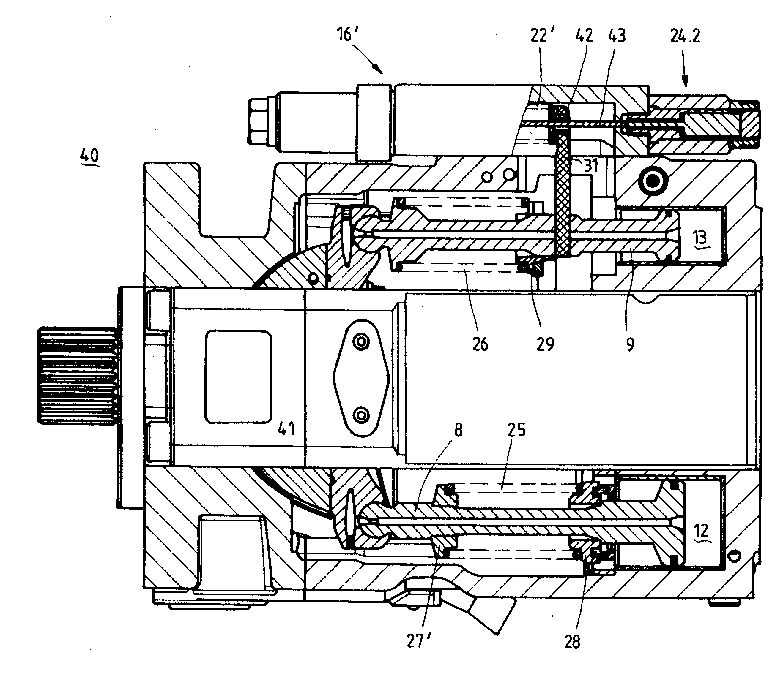
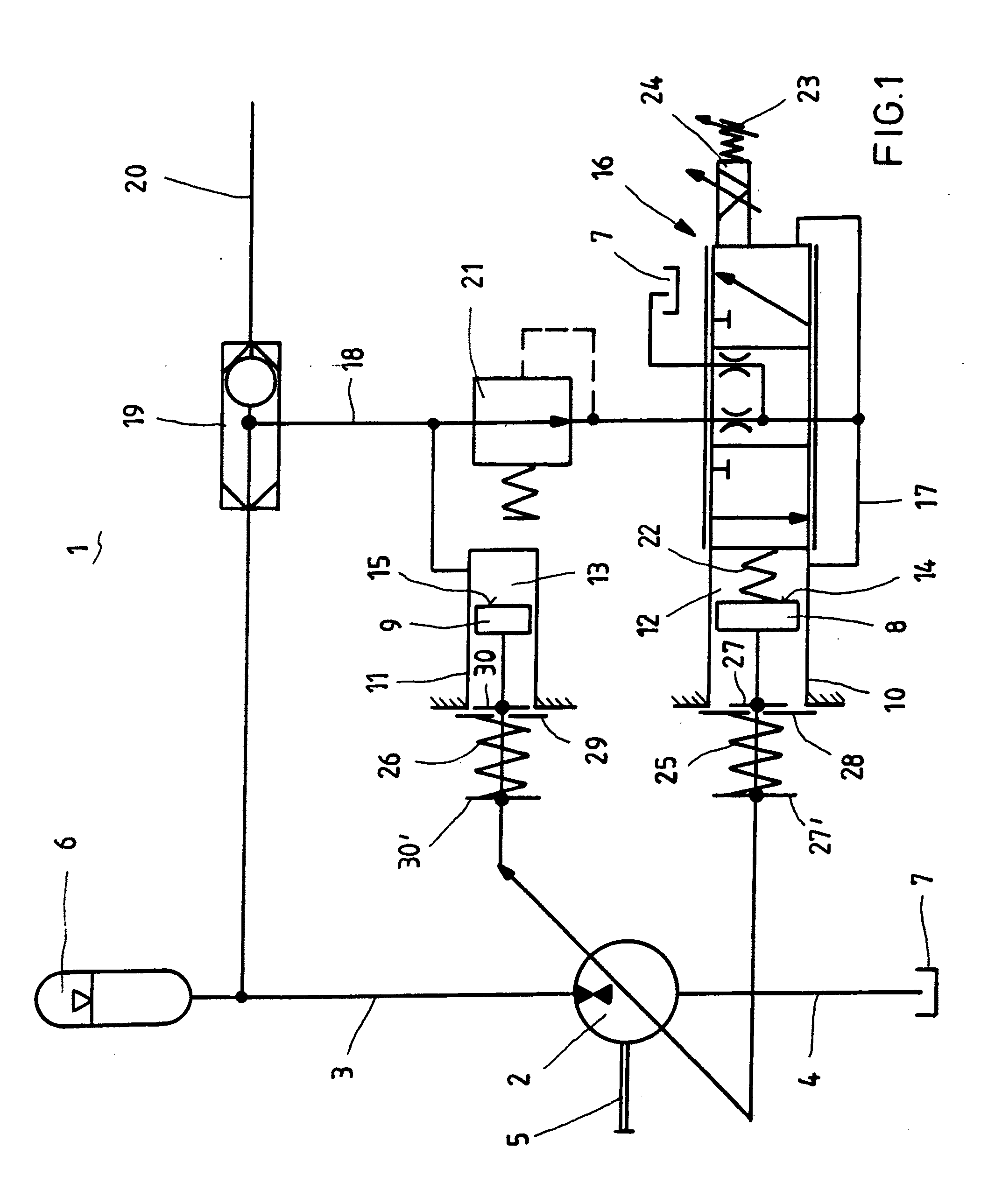
[0030]In accordance with a first exemplified embodiment, the hydrostatic system 1 in accordance with the invention comprises a hydrostatic machine 2. The hydrostatic machine 2 is designed as a pump / motor machine. The hydrostatic machine 2 is designed to be adjustable in terms of its displaced volume and is preferably a hydrostatic axial piston machine in a swash-plate construction which can be pivoted out of a neutral position in two directions. The displaced volume is adjusted by an adjustment of the swash-plate. In the illustrated example, the hydrostatic machine 2 is connected to a first working line 3 and a second working line 4. The first working line 3 connects the hydrostatic machine 2 to a hydraulic accumulator 6. In contrast, the second working line 4 is connected to a tank volume 7. Alternatively, a high pressure accumulator can also be provided as a hydraulic accumulator 6 and a low pressure accumulator can be provided instead of the tank volume 7.

[0031]The hydrostatic ma...


PUM


Abstract

A hydraulic system with an adjustable hydrostatic machine is provided that includes an adjustment mechanism. The adjustment mechanism interacts with an actuating device which has at least one actuating piston delimiting an actuating pressure space. The system has a regulating valve with which, for the displacement of the actuating piston and therefore for the actuation of the adjustment device, the supply and removal of pressure medium into and from the actuating pressure chamber can be controlled, wherein the regulating valve has a valve piston which is subjected to a force of a feedback spring, which force is dependent on the position of the adjustment mechanism. The valve piston is additionally subjected to a counterforce acting counter to the force of the feedback spring, and an actuating component is provided, with which the valve piston can be subjected to a control force acting in the same direction as the counterforce or to a control force acting counter to the counterforce.

Description

[0001]This nonprovisional application is a continuation of International Application No. PCT / EP2008 / 006851, which was filed on Aug. 20, 2008, and which claims priority to German Patent Application No. 10 2007 039 173.2, which was filed in Germany on Aug. 20, 2007, and which are both herein incorporated by reference.BACKGROUND OF THE INVENTION[0002]1. Field of the Invention[0003]The invention relates to a hydraulic system having an adjustable hydrostatic machine, an adjusting device which cooperates with the hydrostatic machine, and a regulating valve, wherein the adjusting device comprises at least a first adjusting piston which is influenced on an adjusting piston surface by an adjusting pressure, and wherein the regulating valve comprises a regulating element which is influenced in the direction of a first end position of the valve by a force dependent upon the position of the first adjusting piston, and which is influenced at a second end by an adjusting force for the purpose of ...

Claims


Application Information

Patent Timeline
Patent Type & Authority Applications(United States)
IPC IPC(8): F01B3/00F04B1/26
CPCF04B1/2014F04B1/324F04B2201/12051F04B2201/12041F04B49/002
Inventor KREBS, CLEMENSNAFZ, TIMO
Owner ROBERT BOSCH GMBH
Why Eureka
Try Eureka