Digital IF Distribution Networks for Radio Communications

Active Publication Date: 2010-08-12
THALES HLDG UK
View PDF8 Cites 30 Cited by
  • Summary
  • Abstract
  • Description
  • Claims
  • Application Information

AI Technical Summary

Benefits of technology

[0015]Embodiments of the invention use a digital data link or network to allow radio frequency (RF) circuitry to be located remotely from the intermediate frequency (IF) and protocol processing circuitry, regardless of the radio standard under consideration. The use of the radio frequency processing unit or units, the digital data link and the intermediate frequency processing units allows a reduction in the physical volume, weight, and power consumption of the radio equipment housed in the equipment bay, while allowing the RF functionality to be placed more flexibility. In particular, embodiments of the invention allow the RF functionality to be placed at, or very close to, the radio antennas themselves. This can have particular advantage for high frequency communications, such as satellite communications systems, where the losses associated in transmitting RF signals between the equipment bay and the antenna may degrade system performance. Some embodiments provide an aircraft radio system in which radio signal processing is distributed over different areas of the aircraft, for example, including next to the antenna installation, and also in a remote area under the floor of the aircraft, or in the pilot's cabin.
[0017]The digital data network in some embodiments relies on the observation that the bandwidth of data to he carried in individual bands, for all existing and proposed radio standards for civil aviation, is less than 65 MHz, as shown in FIG. 1. This makes feasible the digitisation of an entire frequency band or sub-band and its subsequent transmission over a high-speed serial digital data link. Furthermore, the relatively low variation in radio system bandwidth of 19 to 65 MHz, as shown in FIG. 1, enables a digital data link to be standardised for use in all radio systems under consideration.

Problems solved by technology

The result is a significant cost in weight, physical volume, and power consumption.

Method used


Image

  • Digital IF Distribution Networks for Radio Communications
  • Digital IF Distribution Networks for Radio Communications
  • Digital IF Distribution Networks for Radio Communications

Examples


Embodiment Construction

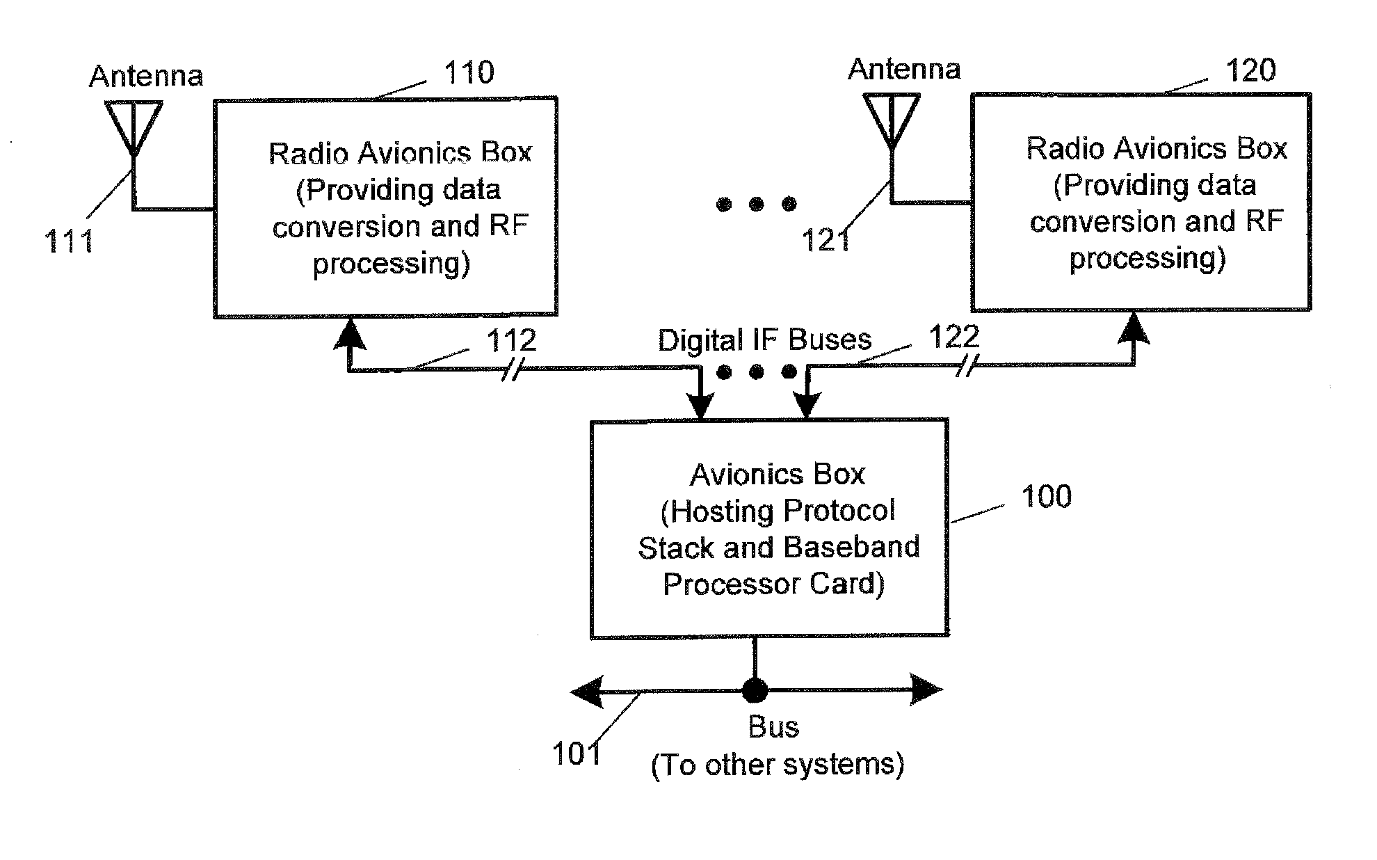
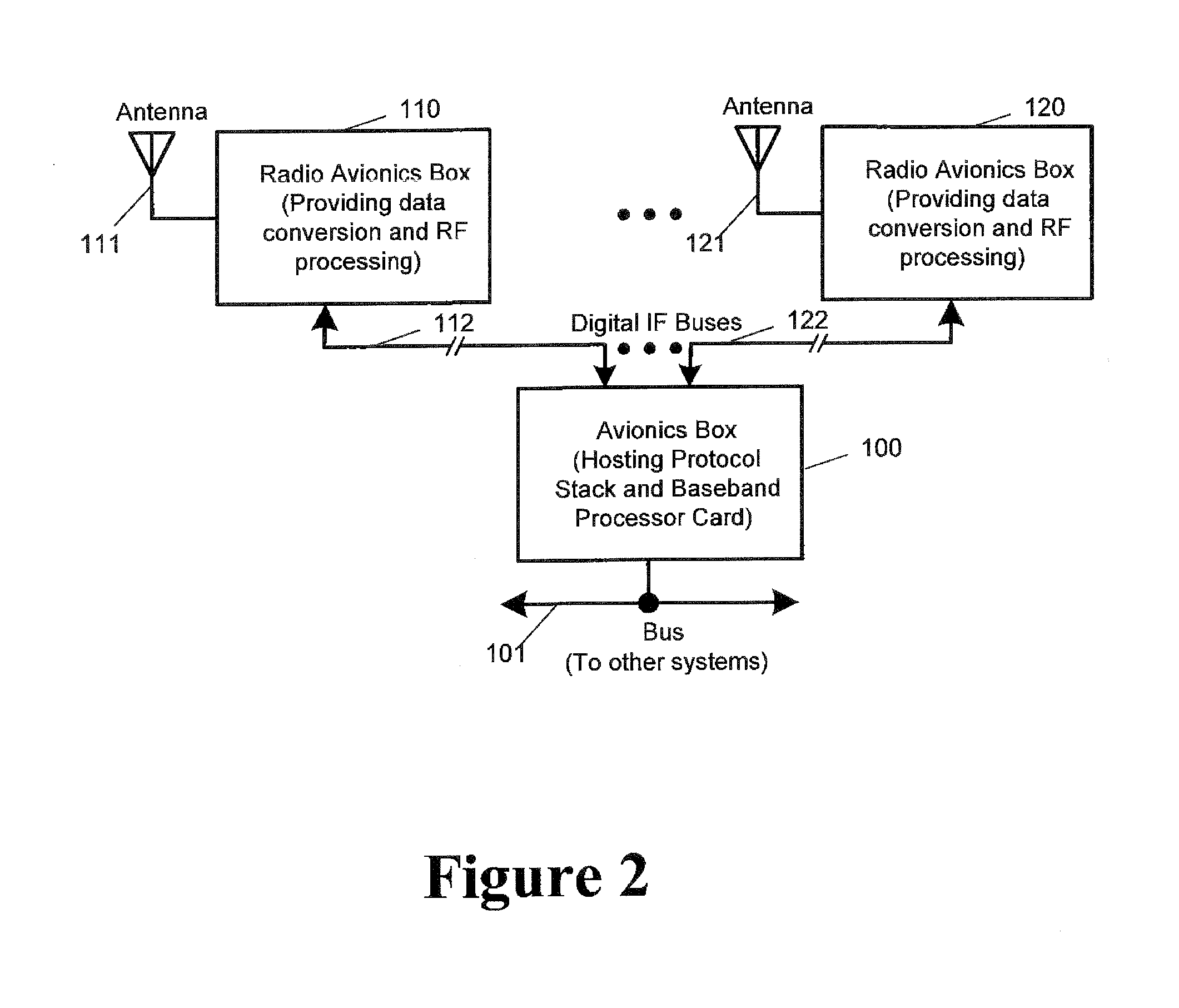
[0029]A first embodiment of the invention is shown in FIG. 2. The system includes a first radio avionics box 110, which is configured for RF processing and data conversion on a first radio frequency band, and a second radio avionics box 120, configured for RF processing and data conversion on a second radio frequency band. A first antenna 111 is connected to the first radio avionics box 110, and a second antenna 121 is connected to the second radio avionics box 120. A first digital IF bus 112 connects the first radio avionics box 110 to a baseband avionics box 100. A second digital IF bus 122 connects the second radio avionics box 120 to the baseband avionics box 100. The baseband avionics box 100 hosts a protocol stack, and includes a baseband processor card. This enables received intermediate frequency signals to be processed according to the radio standard which they are using. The baseband avionics box 100 may be connected to an AFDX bus (Avionics Full Duplex Switched Ethernet) ...


PUM


Abstract

A radio apparatus comprising: a radio frequency processing module for converting radio frequency signals from an antenna to intermediate frequency signals; an intermediate frequency processing module located remotely from the radio frequency processing module, for receiving intermediate frequency signals and processing said signals according to at least one communications protocol; and a digital data link for connecting the radio frequency processing module and the intermediate frequency processing module, for transfer of the intermediate frequency signals.

Description

PRIORITY CLAIM[0001]This application claims priority to United Kingdom Patent Application Number 0902182.5, Digital Distribution Network for Radio Communications, filed Feb. 10, 2009.FIELD OF THE INVENTION[0002]The present invention relates to apparatus and methods for radio communications, which may include SDR (software defined radio) technology.BACKGROUND OF THE INVENTION[0003]Radio installations in aircraft are required to simultaneously process many different radio standards, relating to many different frequency bands and modulation types. FIG. 1 shows a table, listing the main radio bands in present use for civil aviation and the bands proposed for future use, together with the operating frequency ranges for each and the bandwidths in use for each. These radio bands include the HF band at 2-30 MHz, VHF at 118-137 MHz, and various bands above 1 GHz such as those used by the Inmarsat, Thuraya, Iridium and GlobalStar systems. Proposed new bands are the L-band at 960-1024 MHz, and...

Claims


Application Information

Patent Timeline
IPC IPC(8): H04B1/00H04B1/06H04B1/04H04L27/00H04L27/06H04B1/38H04B1/40
CPCH04B1/0075H04B1/0007H04B7/18506H04B1/0071H04B1/26H04B1/40H04B7/18502
Inventor HARRIS, PHILIP J.
Owner THALES HLDG UK
Why Eureka
Try Eureka