Method for manufacturing field-effect transistor
a field-effect transistor and manufacturing method technology, applied in the direction of basic electric elements, electrical apparatus, semiconductor devices, etc., can solve the problems of difficult to increase electron mobility, the inability of the zno-based compound to form a stable amorphous phase at room temperature, etc., to reduce parasitic resistance, increase the conductivity of the oxide semiconductor layer, and reduce the effect of parasitic resistan
- Summary
- Abstract
- Description
- Claims
- Application Information
AI Technical Summary
Benefits of technology
Problems solved by technology
Method used
Image
Examples
embodiment 1
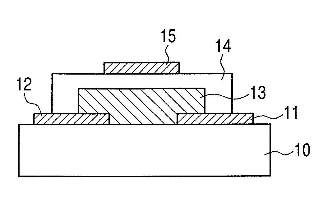
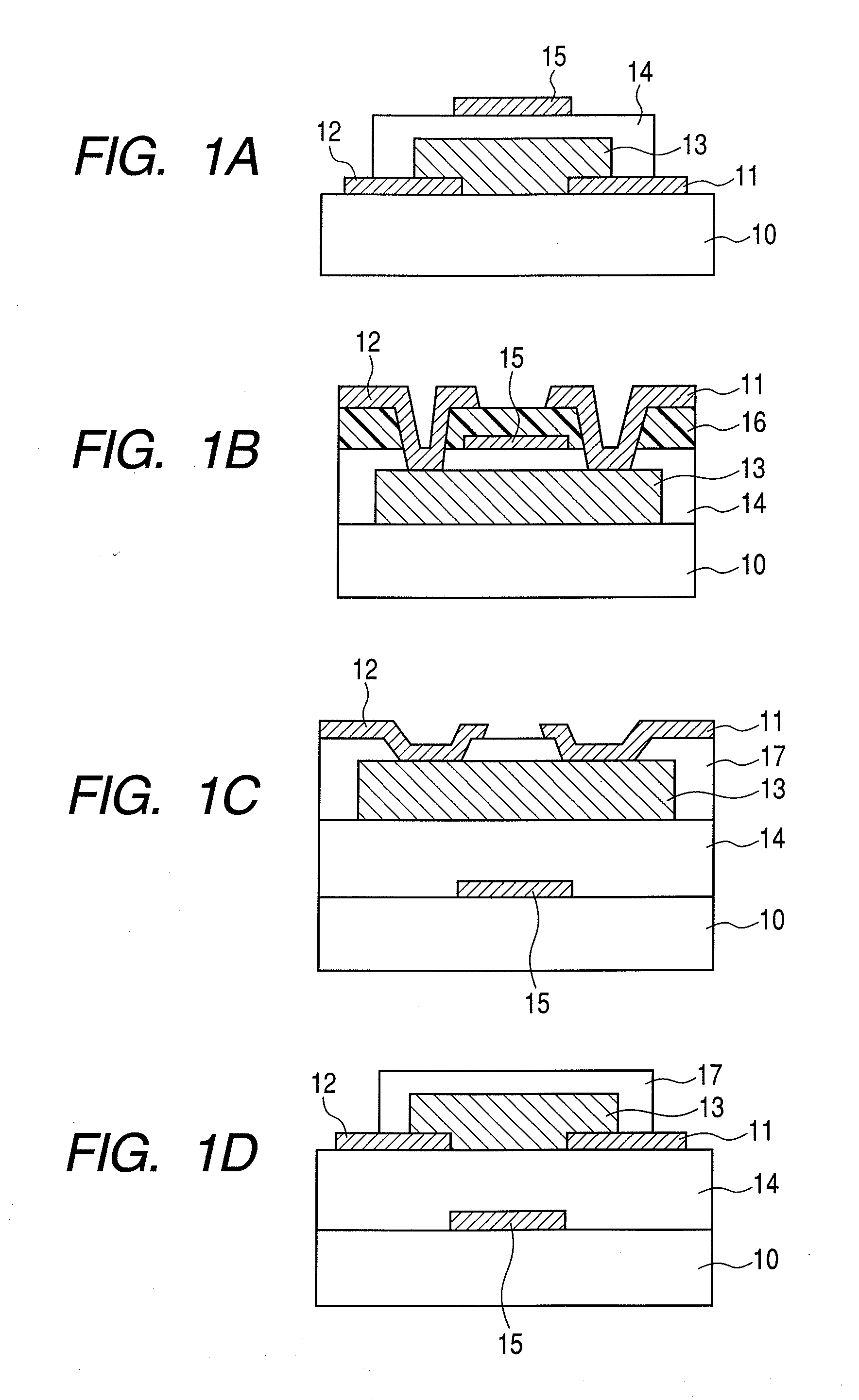
[0068]FIG. 1A illustrates a method for manufacturing a top-gate stagger field-effect transistor.
[0069]An electrode layer for forming a source electrode and a drain electrode is formed on a glass substrate 10 (1737, manufactured by Corning Inc.) by sputtering. The electrodes are formed of indium tin oxide (ITO) and have a thickness of 50 nm.
[0070]Then, the electrode layer is patterned by photolithography and etching to form the source electrode 11 and the drain electrode 12.
[0071]Next, an In—Zn—Ga—O oxide amorphous semiconductor layer 13 having a thickness of 30 nm is formed on the glass substrate 10 having the source electrode 11 and the drain electrode 12. The oxide semiconductor layer is formed with a radio frequency (RF) sputtering apparatus at a substrate temperature of room temperature (25° C.). A target is a three-inch polycrystalline sintered compact having an In2O3.ZnO composition. The RF input power is 200 W. The total pressure of the atmosphere when the film is formed is 0...
embodiment 2
[0077]FIG. 1B illustrates a method for manufacturing a top-gate / top-contact field-effect transistor.
[0078]First, an In—Zn—Ga—O amorphous oxide semiconductor layer 13 is formed at a thickness of 50 nm on the glass substrate 10 (1737, manufactured by Corning Inc.) illustrated in FIG. 1B. The oxide semiconductor film is formed by an RF sputtering apparatus with the substrate temperature of room temperature (25° C.). A three-inch polycrystalline sintered compact having an In2O3.ZnO composition is used as the target, and the RF input power is 200 W. The total pressure of the atmosphere when the film is formed is 0.5 Pa, and the gas flow rate at that time is Ar:O2=93:7. After that, photolithography technology and etching technology are used to pattern the oxide semiconductor layer 13.
[0079]Next, the gate insulating layer 14 and a gate electrode 15 are formed.
[0080]The gate insulating layer 14 is formed of SiO2 as a target by sputtering and has a thickness of 100 nm. The gate insulating la...
embodiment 3
[0085]FIG. 1C illustrates a method for manufacturing a bottom-gate top-contact field-effect transistor.
[0086]First, the gate electrode 15 is patterned and formed on the substrate 10 (1737, manufactured by Corning Inc.) using photolithography technology and etching technology. The electrode is formed of Mo at a thickness of 50 nm on the glass substrate 10 by sputtering.
[0087]Next, with regard to the gate insulating layer 14, SiO2 is used as the target, and an SiO2 film with a thickness of 200 nm is formed by sputtering. Further, an In—Zn—Ga—O amorphous oxide semiconductor material with a thickness of 30 nm is used as the oxide semiconductor film 13.
[0088]The oxide semiconductor film is formed by using an RF sputtering apparatus with the substrate temperature of room temperature (25° C.). A three-inch polycrystalline sintered compact having an In2O3ZnO composition is used as the target, and the RF input power is 200 W. The total pressure of the atmosphere when the film is formed is 0....
PUM
| Property | Measurement | Unit |
|---|---|---|
| pressure | aaaaa | aaaaa |
| thickness | aaaaa | aaaaa |
| thickness | aaaaa | aaaaa |
Abstract
Description
Claims
Application Information
 - R&D
- Intellectual Property
- Life Sciences
- Materials
- Tech Scout
- Unparalleled Data Quality
- Higher Quality Content
- 60% Fewer Hallucinations
Browse by: Latest US Patents, China's latest patents, Technical Efficacy Thesaurus, Application Domain, Technology Topic, Popular Technical Reports.
© 2025 PatSnap. All rights reserved.Legal|Privacy policy|Modern Slavery Act Transparency Statement|Sitemap|About US| Contact US: help@patsnap.com


