Casing Inspection Logging Tool

a technology of logging tool and casing, which is applied in the direction of instruments, survey, borehole/well accessories, etc., can solve the problems of high resolution and achieve the effects of simple construction, greater accuracy, and more rugged design

Inactive Publication Date: 2010-08-19
HUNTING TITAN +1
View PDF3 Cites 32 Cited by
  • Summary
  • Abstract
  • Description
  • Claims
  • Application Information

AI Technical Summary

Benefits of technology

[0015]A principle advantage of the present invention is its greater accuracy, which reveals far more information about the condition of the casing than heretofore available. Moreover, this information is provided more rapidly, and in the first pass through the casing, which negates the need to make repeat measurements. Other important advantages include simpler construction, operation at higher temperatures, more rugged design, high reliability, and lower cost to manufacture and to use in the field.
[0016]In one embodiment of the invention, there is provided an instrument assembly for a well casing inspection tool, comprising a main shaft having a hollow portion and an extension shaft extending axially from a first end of the main shaft, and an instrument head concentric with and configured for free rotation about the extension shaft and proximate the first end of the main shaft. The rotating instrument head provides continuous 360 degree scanning of the interior of the well casing to obtain detailed measurements of the well casing.
[0017]In another embodiment of the invention, there is provided a well casing inspection instrument, comprising an elongated instrument body having a longitudinal axis, a main shaft supported in the elongated body along said axis, a motor mounted in the main shaft and aligned along the longitudinal axis, a rotating sensor assembly supported by a bearing assembly on an extension of the main shaft and driven by the motor; wherein the rotating sensor assembly provides continuous 360 degree scanning of the interior of the well casing to obtain detailed measurements of the well casing.
[0018]In another embodiment of the invention, there is provided a casing inspection tool, comprising a tool body, a main shaft having a first diameter and a first end and disposed in the tool body, the main shaft having a hollow first portion proximate the first end; an extension shaft of smaller diameter extending longitudinally from the first end of the main shaft; and a rotating sensor assembly supported on the extension shaft by a bearing assembly and driven by a DC brushless motor supported within the hollow portion of the main shaft, the sensor assembly further including a high resolution wall thickness sensor for scanning the entire wall of the casing to obtain continuous detailed wall thickness data, and a high resolution caliper sensor for scanning the entire wall of the well casing to obtain continuous detailed caliper data.
[0019]In another embodiment of the invention, a signal coupling apparatus is provided for coupling electrical signals across a gap between two closely mounted assemblies. The apparatus comprises first and second flat conductive rings disposed on respective first and second planar substrates, the conductive rings centered on a common axis and disposed in a facing, spaced apart relationship across a defined gap, wherein the conductive rings form respective plates of a capacitor.
[0020]In several aspects of the inventions, the instrument head includes sensors for measuring wall thickness and caliper of the well casing, and a motor drives the rotating instrument head through a gear train. The rotating instrument head is supported on bearings on the extension shaft. A mandrel supported by the main shaft includes exciter coils for wall thickness, caliper, and permeability measurements. A capacitive slip ring couples signals between the rotating instrument head and stationary circuits in the instrument assembly.

Problems solved by technology

The logging tool provides a greater number of data points produced by relatively smaller receiver coils placed very close to the casing wall, resulting in high resolution of casing anomalies and such defects as corrosion, pitting, fractures, material voids, and the like.

Method used


Image

  • Casing Inspection Logging Tool
  • Casing Inspection Logging Tool
  • Casing Inspection Logging Tool

Examples


Embodiment Construction

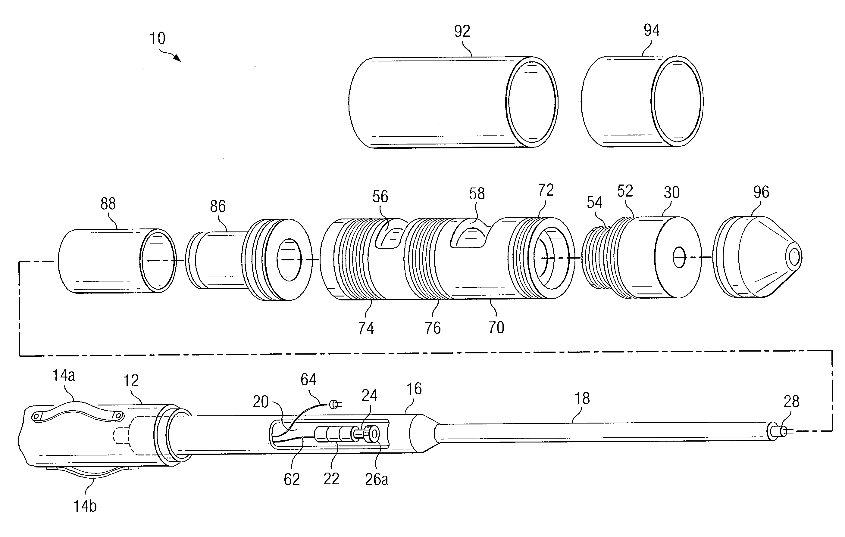
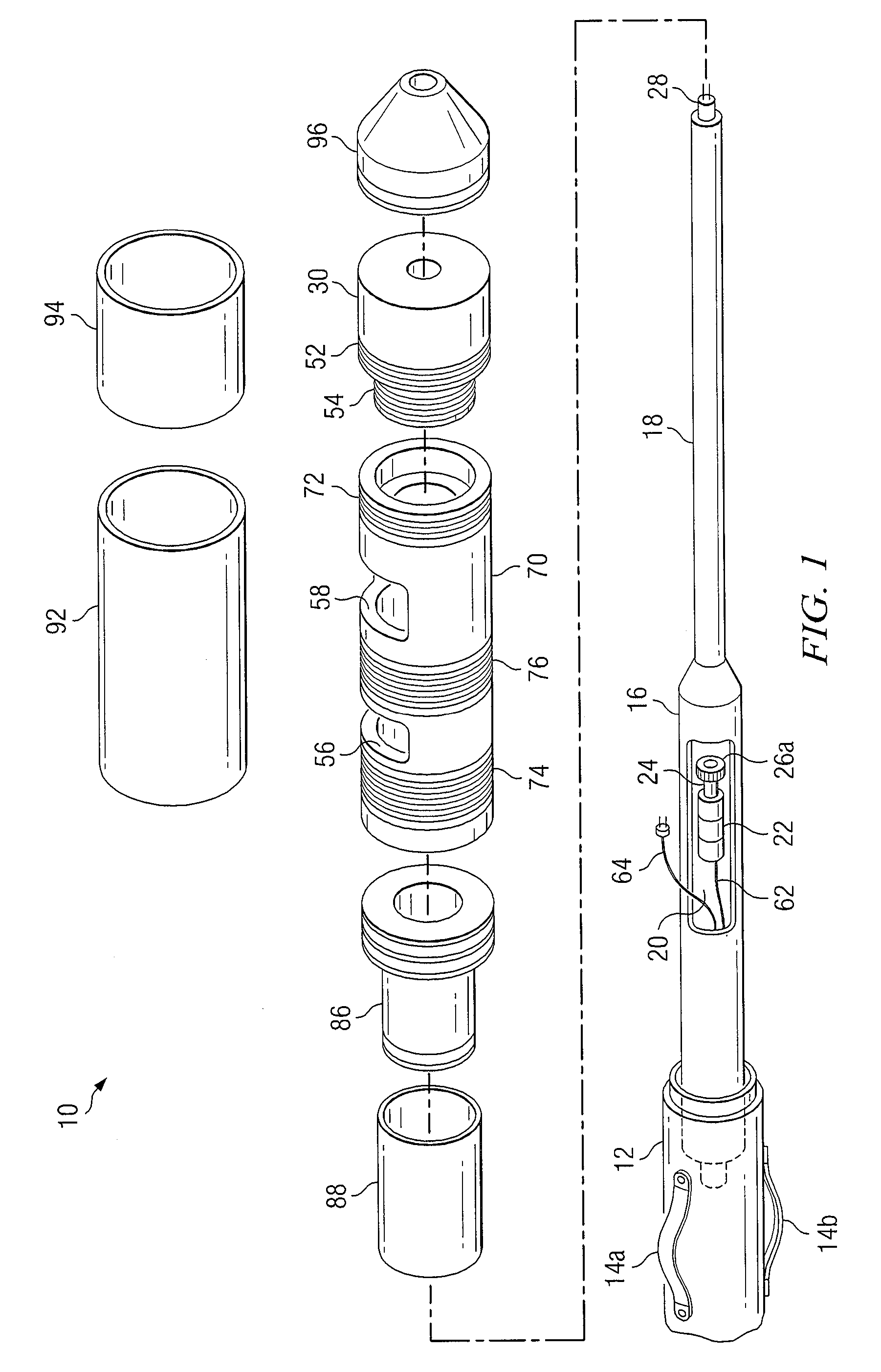
[0036]By way of introduction, the present invention is an instrument assembly for a well casing inspection tool. The invention includes sensing coils for making measurements of characteristics of the well casing that are disposed in a rotating portion of the tool to enable continuous 360 degree scanning of the interior of a well casing. By configuring the sensor head to place the sensing coils close to the well casing inner surface and to continuously scan the inner wall of the well casing at relatively high speed, the instrument obtains high resolution data for the entire casing, not just sampled data at regular but spaced apart intervals.

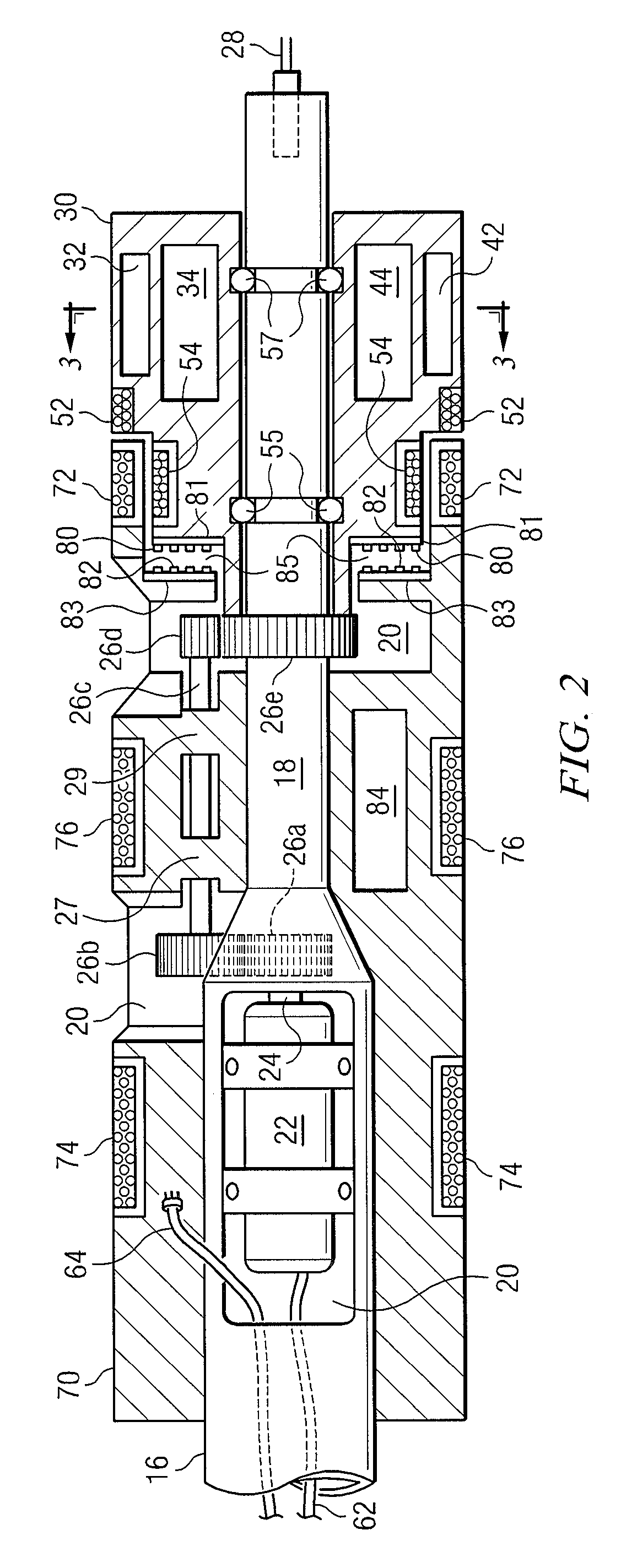
[0037]The instrument for a well casing inspection tool to be described herein comprises an elongated cylindrical body or mandrel that surrounds a stationary main shaft. The longitudinal axis of the main shaft defines the longitudinal axis of the instrument. Extending axially (along the longitudinal axis) from a first end of the main shaft is a sma...


PUM


Abstract

An instrument assembly for a well casing inspection tool, comprising a main shaft having an extension shaft extending therefrom. An instrument head is supported on bearings proximate one end of the main shaft. The rotating instrument head, which includes sensors for measuring wall thickness and caliper of the well casing, provides continuous 360 degree scanning of the interior of the well casing to obtain detailed measurements of the well casing. A motor drives the rotating instrument head through a gear train. A mandrel supported by the main shaft includes exciter coils for wall thickness, caliper, and permeability measurements. A capacitive slip ring couples signals between the rotating instrument head and stationary circuits in the instrument assembly.

Description

[0001]The present application is related to co-pending U.S. patent application by the same inventor entitled “Capacitive Signal Coupling Apparatus,” filed concurrently herewith.BACKGROUND OF THE INVENTION[0002]1. Field of the Invention:[0003]The present invention generally relates to down-hole oil and gas logging instruments and more particularly to logging tools for measuring the inside diameter and wall thickness of the well casing in oil and gas wells and in other applications where these parameters of such pipe must be inspected and measured.[0004]2. Background and Description of the Prior Art:[0005]Well casings and other metallic pipe (“casing”) used in down-hole drilling for oil and gas and, more recently, for geothermal fluids, typically encounters severe conditions of chemical, temperature and pressure phenomena. These conditions subject the casing to corrosion and other types of deterioration from the fluids and other caustic substances that flow through them or which exist...

Claims


Application Information

Patent Timeline
Patent Type & Authority Applications(United States)
IPC IPC(8): E21B33/04
CPCE21B47/01G01B7/13G01B7/10E21B47/082E21B47/085
Inventor ESTES, JAMES D.
Owner HUNTING TITAN
Why Eureka
Try Eureka