
Body contacts for fet in soi SRAM array

Active Publication Date: 2010-08-19
GLOBALFOUNDRIES US INC
View PDF6 Cites 40 Cited by
  • Summary
  • Abstract
  • Description
  • Claims
  • Application Information

AI Technical Summary

Benefits of technology

[0057]It is a general object of the invention to provide an i

Problems solved by technology

Back biases may be applied to SOI FETs through a contact to the underlying layer (or body contact) that may require as much area as the FET itself and may make circuit wiring more difficult.
Unfortunately, as body contacts are eliminated or at the very least shared by more and more devices, individual devices become much more susceptible to localized device phenomena known as body effects.
Localized body effect variations cause device non-uniformity.
Device leakage and parasitic bipolar effects may add to the charge.
So, body effects may cause two devices that are identical by design may exhibit some difference, difference that may be time varying from changing circuit conditions.
These localized body effects and other sporadically occurring parasitic bipolar effects, i.e., at source / drain diffusion junctions, are serious design problems for densely packed SOI circuits such as for example, memory arrays, e.g., a Static RAM (SRAM) macro.
However, SOI FETs have a “floating body.” The body or channel region of the FET is formed in an insulated pocket of silicon and is therefore not electrically connected to a fixed potential.
This is a particular problem in a SRAM cell as lowering the VT of the devices can cause the relative strengths of devices to change such that the cell flips when the state of the latch is read.
The charge accumulates on this capacitor and may cause adverse effects, for example, opening of parasitic transistors in the structure and causing off-state leakages, resulting in higher current consumption and in case of DRAM in loss of information from the memory cells.
However, the short-channel effect is worsened in the FD devices, the body may still charge up if both source and drain are high, and the architecture is unsuitable for some analog devices that require contact with the body.
However, SRAM is still volatile in the (conventional) sense that data is lost when powered down.

Method used


Image

  • Body contacts for fet in soi SRAM array
  • Body contacts for fet in soi SRAM array
  • Body contacts for fet in soi SRAM array

Examples


Embodiment Construction

[0090]In the description that follows, numerous details are set forth in order to provide a thorough understanding of the present invention. It will be appreciated by those skilled in the art that variations of these specific details are possible while still achieving the results of the present invention. Well-known processing steps and materials are generally not described in detail in order to avoid unnecessarily obfuscating the description of the present invention.

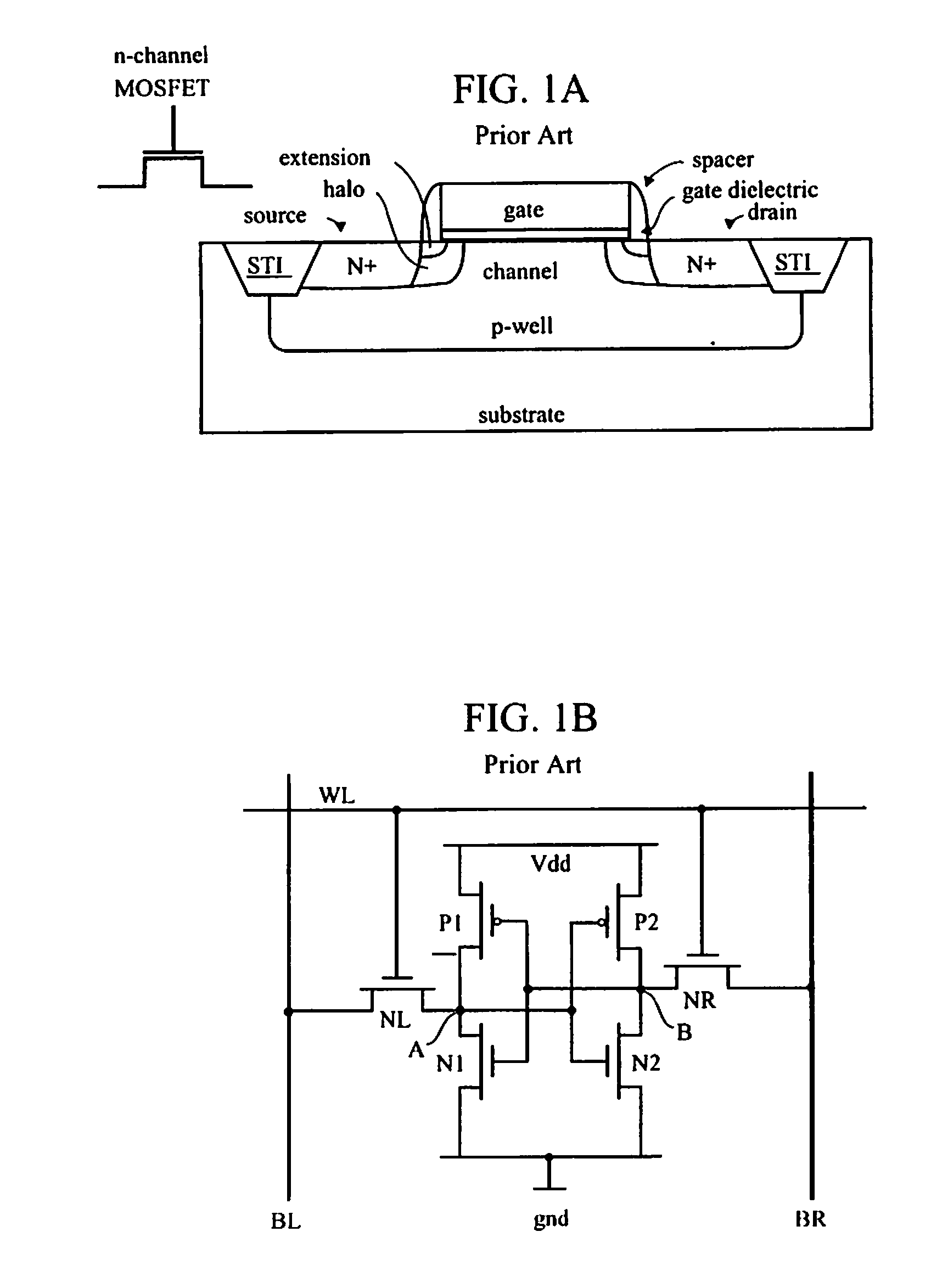
[0091]Bulk silicon is currently in wider use than silicon on insulator (SOI). SOI uses a thin film, capacitance is low, and there is no path from source / drain (S / D) to the body so the leakage is low. However, floating body effects may impair device performance. Making contact with the body of SOI FETs may reduce floating body effects, but is difficult to implement in SRAM array without sacrificing cell area. Linking body contacts provide significant reduction of variation across memory cells across an array. Body contac...


PUM


Abstract

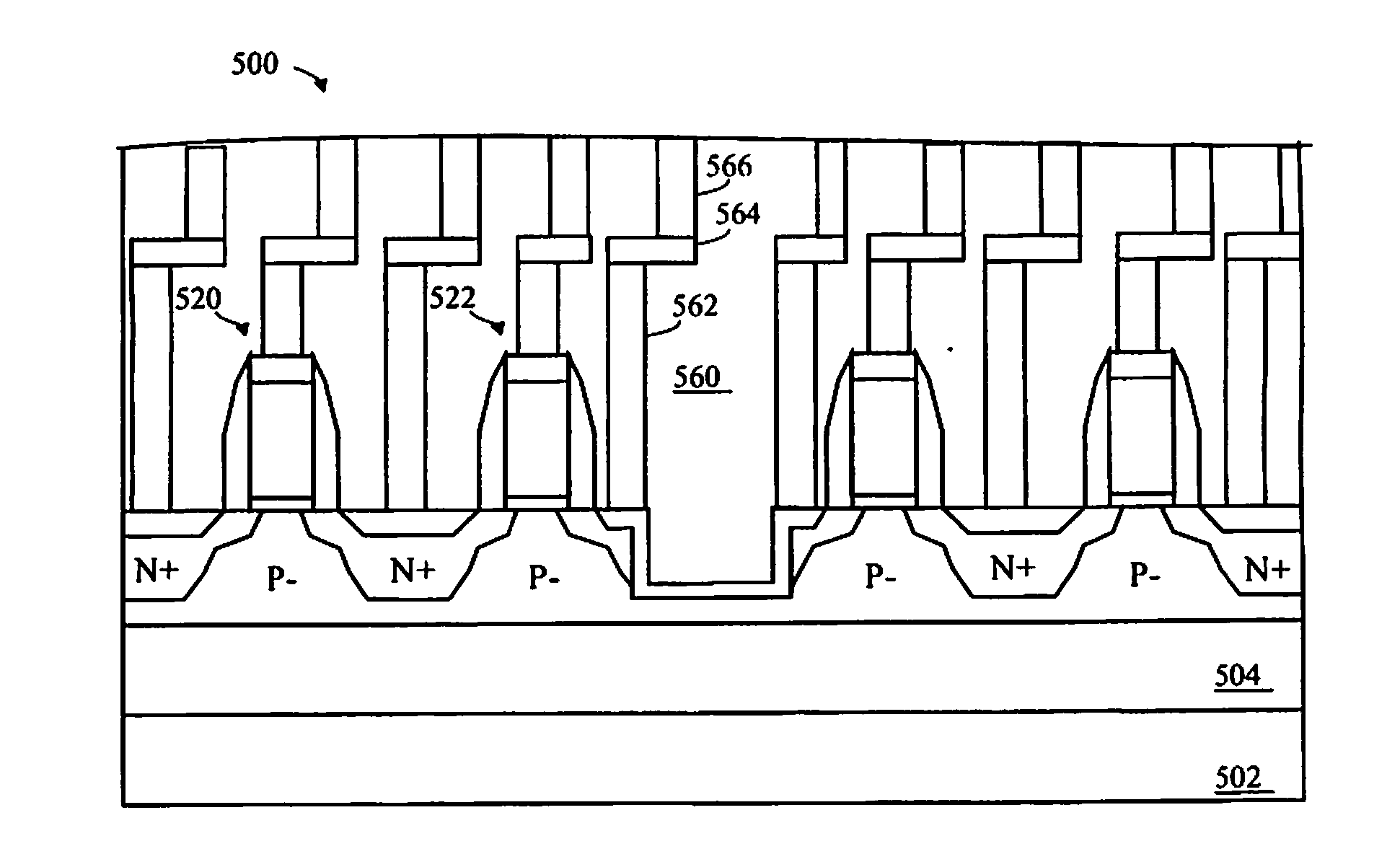
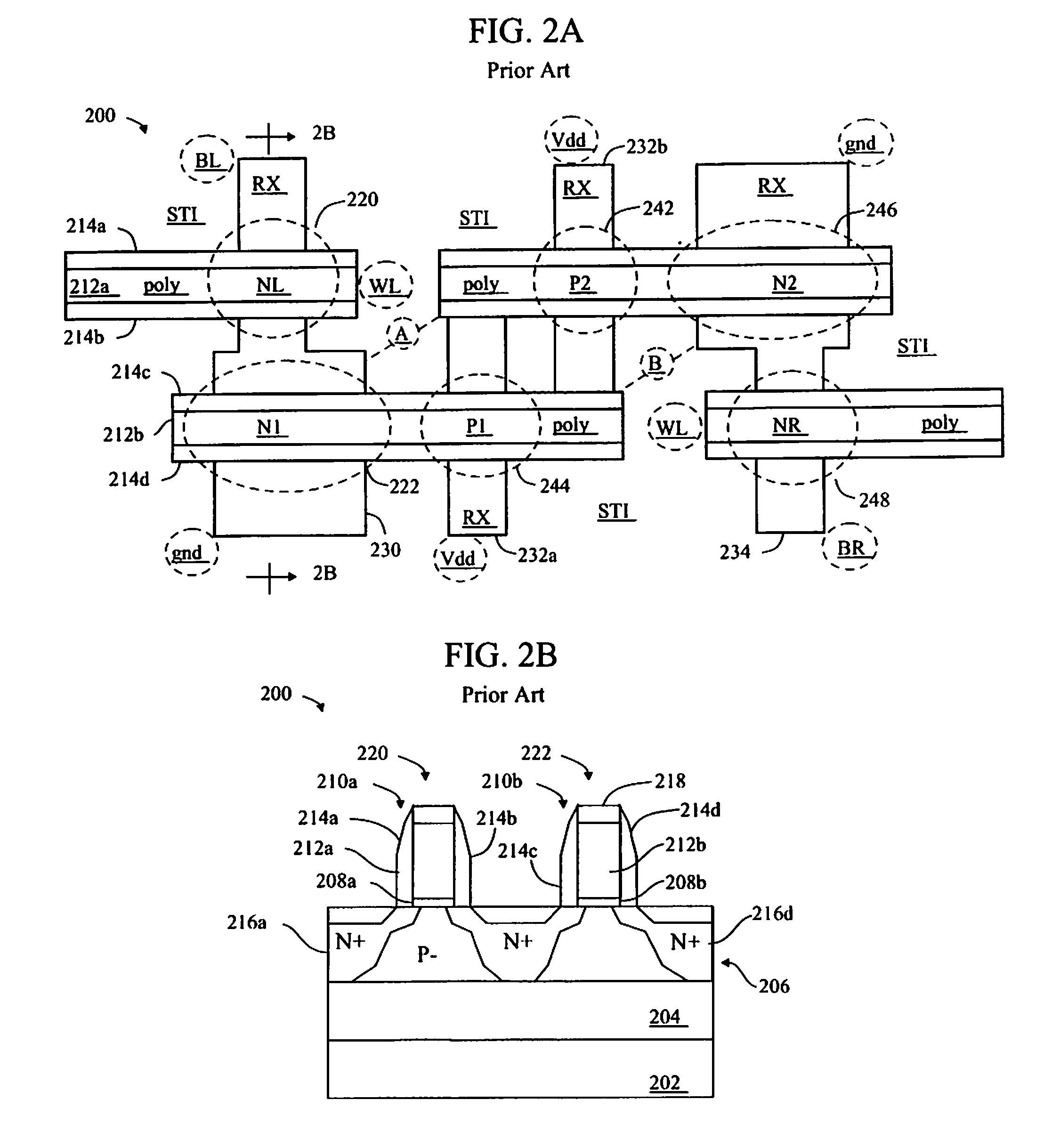
Contact with a floating body of an FET in SOI may be formed in a portion of one of the two diffusions of the FET, wherein the portion of the diffusion (such as N−, for an NFET) which is “sacrificed” for making the contact is a portion of the diffusion which is not immediately adjacent (or under) the gate. This works well with linked body FETs, wherein the diffusion does not extend all the way to BOX, hence the linked body (such as P−) extends under the diffusion where the contact is being made. An example showing making contact for ground to two NFETs (PG and PD) of a 6T SRAM cell is shown.

Description

[0001]This non-provisional application claims the benefit of the provisional application filed with the United States Patent and Trademark Office as Ser. No. 61 / 153,467 entitled “BODY CONTACTS FOR FET IN SOI SRAM ARRAY” filed Feb. 18, 2009.FIELD OF THE INVENTION[0002]The invention relates to semiconductor device fabrication and, more particularly, to making body contacts to field effect transistors (FETs), such as FETs formed in silicon on insulator (SOI) substrates, such as FETs in a static random access memory (SRAM) cell.BACKGROUND OF THE INVENTION[0003]The transistor is a solid state semiconductor device which can be used for amplification, switching, voltage stabilization, signal modulation and many other functions. Generally, a transistor has three terminals, and a voltage applied to a specific one of the terminals controls current flowing between the other two terminals. One type of transistor is known as the field effect transistor (FET).[0004]The terminals of a field effect...

Claims


Application Information

Patent Timeline
IPC IPC(8): H01L27/12H01L21/86
CPCH01L21/743H01L21/84H01L27/11H01L29/7841H01L27/1203H01L29/7833H01L27/1108H10B10/00H10B10/125
Inventor TAN, YUEREN, ZHIBINWACHNIK, RICHARD A.YANG, HAINING S.
Owner GLOBALFOUNDRIES US INC
Learn More