Method and apparatus for determining the thermal expansion of a material

a technology of thermal expansion and material, applied in the direction of material thermal analysis, measurement devices, instruments, etc., can solve the problem that the technique cannot be used in the case of particle formation

Inactive Publication Date: 2010-08-19
CONSEJO NAT DE INVESTIGACIONES CIENTIFICAS Y TECH CONICET
View PDF23 Cites 19 Cited by
  • Summary
  • Abstract
  • Description
  • Claims
  • Application Information

AI Technical Summary

Benefits of technology

[0009]It has been found that said focus error signal, when appropriately calibrated, gives a very accurate and sensitive measurement of the magnitude of the expansion. Said magnitude and its dependence with the modulation frequency allows for the determination either the thermal expansion coefficient, or the thermal diffusivity, the thickness of coating film or the absorption coefficient of light on the heating beam.

Problems solved by technology

Said technique cannot be used in case the particle is in a dry environment, deposited on the surface or in case a nanometric or micrometric device such as the ones used in photonics or microelectronics.

Method used


Image

  • Method and apparatus for determining the thermal expansion of a material
  • Method and apparatus for determining the thermal expansion of a material
  • Method and apparatus for determining the thermal expansion of a material

Examples


Embodiment Construction

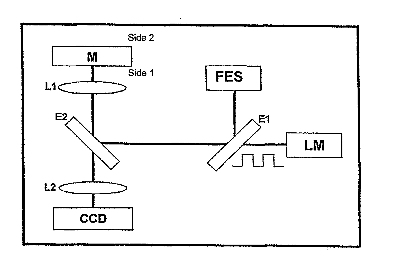
[0019]A mechanism of modulated localized heating in time at a controlled frequency, preferably a laser, produces the periodic expansion of material at the modulation frequency. Said expansion depends on the absorbed power, spatial dimensions of the heating mechanism and the heating frequency, as known, as it was described in prior art. In accordance with the present invention, a focus error sensing device is used for measuring the expansion of the surface, since being it displaced by means of heat, it is set aside of the correct focus as established in the focus error sensing device. The focus error signal is then a measure for displacement of the surface and therefore its thermal expansion.

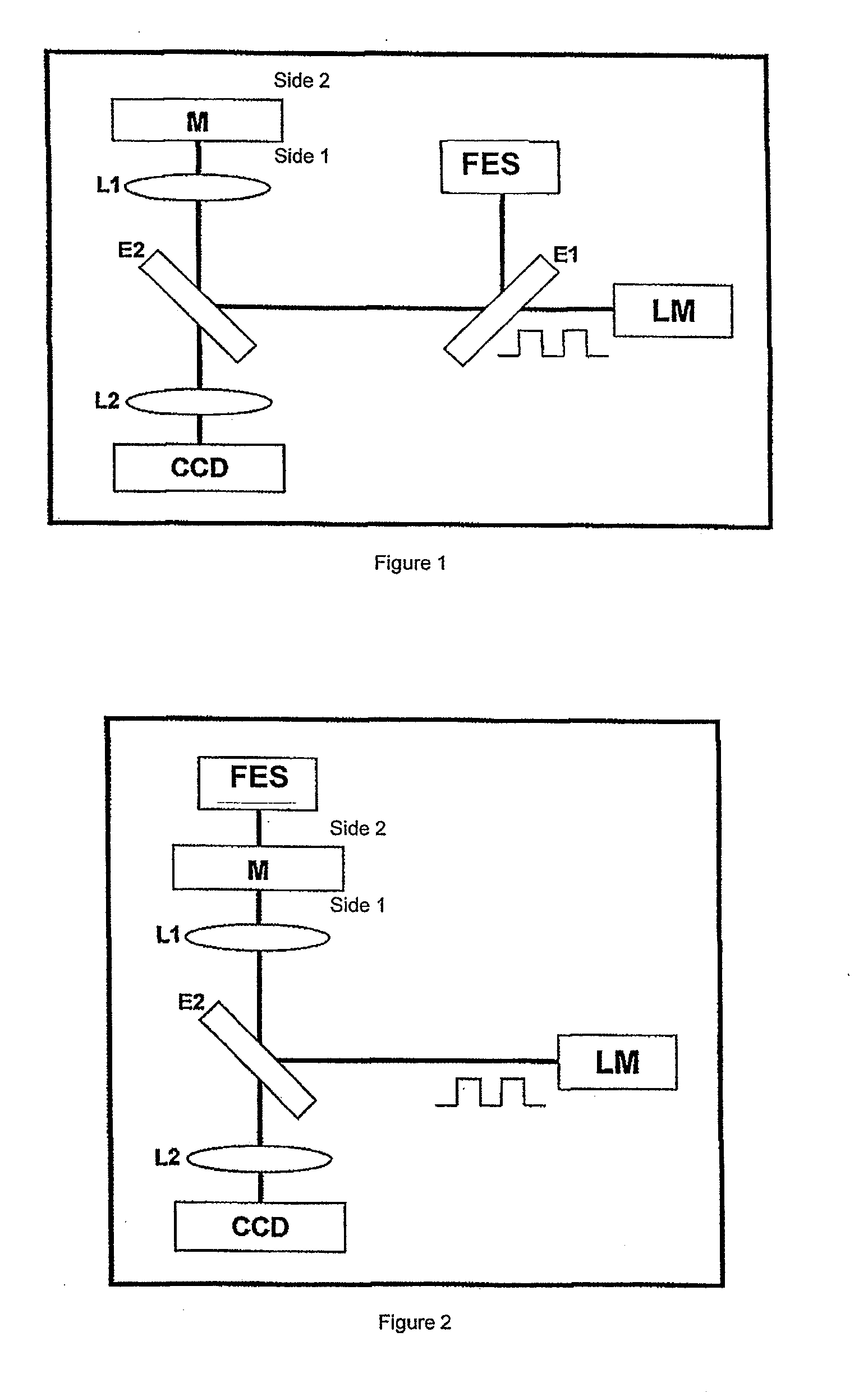
[0020]FIG. 1 shows an apparatus according to the present invention provided with an LM modulated laser source directed by means of dicroic mirror E1 and a beam splitter E2 to the test sample M. The beam splitter is a mirror E2 which partially reflects the wave length for the emission of LM laser....


PUM

PropertyMeasurementUnit
lengthaaaaaaaaaa
thicknessaaaaaaaaaa
thicknessaaaaaaaaaa

Abstract

A focus error signal resulting from the photothermically-induced expansion is measured in a sample of material under analysis. A laser is disposed as a periodically modulated heating source which is directed to the sample and a device for focus error measuring which is directed to de surface being heated. A device measuring focus error generates a signal representative of the displacement of the surface of material in perpendicular direction due to the expansion produced by the periodic heating, which is filtered, either analogically or digitally, to discriminate the displacement component at the frequency in which it was modulated or at any other related frequency, such any harmonic or a sum with any other modulation. The focus error signal, appropriately calibrated, gives a precise and sensitive measure of the magnitude the expansion. Said magnitude and its dependence with the modulation frequency allows the determination of physical properties such as the thermal expansion or thermal diffusivity coefficient, the thickness of a coating film or the absorption coefficient of the light from the heating beam. By varying the wave length of the directed radiation it is possible to determine the absorption spectrum of the sample even for very small sized particles in which the fraction of absorbed energy is very little.

Description

TECHNICAL FIELD OF THE INVENTION[0001]The present invention refers to the characterization without contact of materials for use in engineering, particularly steels and other metals, for the measurement of thermal properties at microscopic scales, in particular thermal expansion coefficients, thermal conductivity, thermal diffusivity and film thicknesses, the characterization of optical properties such as absorption spectra and dispersion of very small devices structured in the scale of nanometers to micrometers and the measurement of absorption spectra of very small particles (in the scale of nanometers to millimeter).PRIOR ART AND PROBLEMS TO BE SOLVED[0002]The determination of thermal parameters (thermal expansion, heat conductivity, thermal diffusivity, etc.) of materials and devices is extremely important to forsee their service applicability. Measurement techniques without contact allow either the detection without damaging the sample or system or the measurement during functio...

Claims


Application Information

Patent Timeline
Patent Type & Authority Applications(United States)
IPC IPC(8): G01N25/16G01N21/25
CPCG01B21/085G01N25/16G01N21/8422G01N21/171
Inventor MART NEZ, OSCAR EDUARDODOMENE, ESTEBAN ALEJOMINGOLO, NELIDABALZAROTTI, FRANCISCOBRAGAS, ANDREA VERONICA
Owner CONSEJO NAT DE INVESTIGACIONES CIENTIFICAS Y TECH CONICET
Why Eureka
Try Eureka