Biochip substrate and process for its production

a biochip and substrate technology, applied in the field of biochip substrate and process for its production, can solve the problems of difficult to accurately detect low density analytes, limited probe choices, and expensive probe design, and achieve accurate and sensitive measurements, and enhance the s/n ratio of fluorescence

Inactive Publication Date: 2005-09-22
ASAHI GLASS CO LTD
View PDF1 Cites 0 Cited by
  • Summary
  • Abstract
  • Description
  • Claims
  • Application Information

AI Technical Summary

Benefits of technology

[0013] The object of the present invention is to provide a biochip substrate which affords accurate and sensitive measurements using a biochip by enhancing the S / N ratio of the fluorescence from each spot.

Problems solved by technology

The fluorescence is weaker than the excitation light, and the maximum and minimum analyte densities in a DNA sample differ by 1000 to 10000 times. Low density analytes are difficult to detect accurately because of the noise such as the fluorescence emission or reflection from the support surface and dirt on it.
However, this approach has problems such as costly probe design and restricted probe choices.
However, there is a problem that films with high probe affinity cost a lot to develop and produce with quality control which ensures film homogeneity over the support surface.
However, this approach is limited to transparent supports and does not improve the S / N ratio as much as theoretically expected because part of the light enters the substrate.
However, because the reflected fluorescence is not directed straight to the fluorescence sensor of the reader, this approach cannot enhance the fluorescence intensity sufficiently.

Method used


Image

  • Biochip substrate and process for its production
  • Biochip substrate and process for its production

Examples


example 1

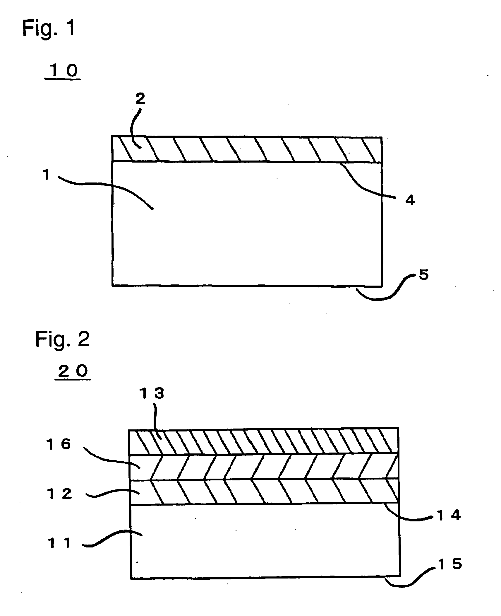
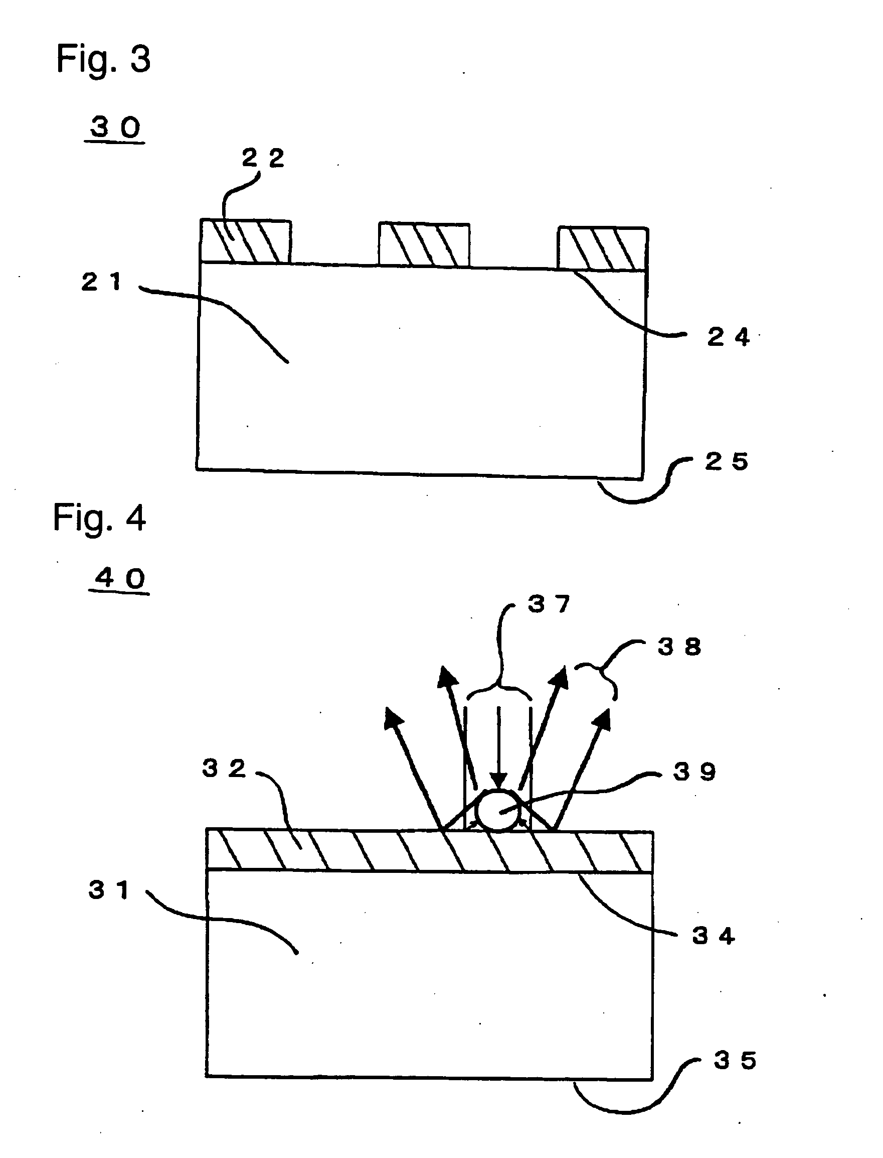
[0050] To a mixture of 2.55 g of Ti(OC4H9)4, 17 g of ethanol and 0.75 g of acetylacetone, 1.1 g of 0.1 mol / dm3 aqueous nitric acid was added dropwise with sufficient stirring. Then, the resulting mixture was stirred at room temperature for 1 hour to make a coating solution. A well-washed glass slide (manufactured by Matsunami Glass) having a thickness of 1 mm, a flatness of 50 μm and a refractive index of 1.5 was dipped in the coating solution for 20 seconds and withdrawn at a rate of 24 cm / min to form a film. It was dried at 120° C. for 15 minutes, baked at 550° C. for 30 minutes to obtain a substrate having a TiO2 film on the surface (hereinafter referred to as the present substrate A). The TiO2 film had a thickness of 100 nm, a surface roughness Ra of 50 nm, a refractive index of 2.4 and a surface resistance of 2×10¹⁰ Ω / □. For comparison, a glass slide coated with poly-L-lysine (hereinafter referred to as comparative substrates) was prepared.

[0051] For comparison of the fluoresc...

example 2

[0053] The procedure in Example 1 was followed except that instead of the substrate A, a present substrate B consisting of a soda lime glass plate having a thickness of 1 mm, a flatness of less than 50 μm and a refractive index of 1.5 and a TiNx coating having a thickness of about 40 nm, a surface roughness Ra of 30 nm, a refractive index of 2.5 and a surface resistance of 2×10¹⁰ Ω / □ formed by sputtering using a Ti target in a gas mixture of Ar and N2 (at a gas flow rate of 30±10 sccm) at a pressure of 133 μPa, a power input of 0.26±0.1 kw and a traveling speed of 2.42±0.5 mm / s without heating the substrate was used, and no comparative substrate was used. The fluorescence was measured, and the fluorescence intensity was high and even over all the spots.

example 3

[0054] The procedure in Example 2 was followed except that a present substrate C prepared by forming a Cr film having a thickness of about 100 nm and a surface resistance of 5×10¹⁰ Ω / □ by sputtering using a Cr target instead of the Ti target under the same sputtering conditions as in Example 2 except that the gas mixture of Ar and N2 was changed to Ar gas, and then forming on the Cr film, a SiO2 film having a thickness of about 10 to 20 nm by sputtering using a Si target in O2 gas (at a gas flow rate of 30±10 sccm) at a pressure of 133 μPa, a power input of 0.26±0.1 kw and a traveling speed of 2.09±0.5 mm / s without heating the substrate was used. The fluorescence was measured, and the fluorescence intensity was high and even over all the spots.


PUM

PropertyMeasurementUnit
refractive indexaaaaaaaaaa
thicknessaaaaaaaaaa

Abstract

The object of the present invention is to provide a biochip substrate which affords accurate and sensitive measurements using a biochip by enhancing the S/N ratio of the fluorescence from each spot. A biochip substrate for producing a biochip by immobilizing a biological high-molecular-weight oligomer, which substantially reflects fluorescence on the surface on which the oligomer is to be immobilized. Preferably, a biochip substrate which consists essentially of a support and a coating formed on the surface of the support on which the biological high-molecular-weight oligomer is to be immobilized, wherein the coating comprises a reflective film which has a higher refractive index than the support.

Description

BACKGROUND OF THE INVENTION [0001] 1. Field of the Invention [0002] The present invention relates to a substrate suitable to make a biochip by arranging and immobilizing trace amounts of biological high-molecular-weight oligomers such as DNA, RNA, sugar chains and proteins corresponding to hundreds to tens thousands of genes. [0003] 2. Discussion of Background [0004] Among biochips, typical are DNA chips having from hundreds to thousands of microspots of numerous DNA fragments immobilized on the substrate. DNA chips are reacted (hybridized) with DNA from human or animals to be examined for numerous DNA sequences to analyze sequence variation among individuals, gene expression in cells in different states and the like. The subsequent description will deal with DNA as a representative, though it also applies to RNA, proteins and sugar chains. [0005] Biochip fabrication is roughly classified on the basis of the method of immobilization of DNA on the substrate, as the photolithographic ...

Claims


Application Information

Patent Timeline
Patent Type & Authority Applications(United States)
IPC IPC(8): C12M1/34C12Q1/68G01N21/64H01L21/00
CPCG01N21/6452
Inventor NOMOTO, HIDEOISHIZEKI, KENJITATEMATSU, SHINISHIMARU, MASAYUKI
Owner ASAHI GLASS CO LTD
Why Eureka
Try Eureka