Yaw controller for downwind wind turbines

a technology of wind turbines and controllers, which is applied in the direction of rotors, marine propulsion, vessel construction, etc., can solve the problems of affecting the rotation speed of the bedplate, the net torque of the tower axis, and damage to the blade of the free yawing machine, so as to prevent unsafe yaw brake release and slow down the rotation speed

Inactive Publication Date: 2010-08-19
MIGLIORI ROBERT
View PDF12 Cites 42 Cited by
  • Summary
  • Abstract
  • Description
  • Claims
  • Application Information

AI Technical Summary

Benefits of technology

[0021]In one aspect, the releasing of the yaw brake is done at least in part based on a wind speed signal, thus preventing unsafe yaw brake release at high wind.
[0022]In another aspect, the releasing of the yaw brake is done such that the yaw brake slows down bedplate rotation at high wind.

Problems solved by technology

However, wind shear causes the blades to sense different wind speeds, thus producing unbalanced aerodynamic forces on the blades, which can result in a net torque about the tower axis.
A free yawing machine is also subject to high yaw rates which can damage turbine blades.
Furthermore, when in the downwind position, the rotating nacelle (or the bedplate that carries the nacelle) is not fixed with respect to the tower.
Those techniques are based on the expensive and potentially unreliable motorized nacelle positioning against the incoming wind.
However, these yaw dampers are passive elements, having no ability to make wind direction measurements or decisions as to the ultimate choice of the yaw angle.
They will slow down, but not prevent the fishtailing.
However, those mechanisms are prone to failures and furthermore have only a limited number of possible yaw angles.

Method used


Image

  • Yaw controller for downwind wind turbines
  • Yaw controller for downwind wind turbines
  • Yaw controller for downwind wind turbines

Examples


Embodiment Construction

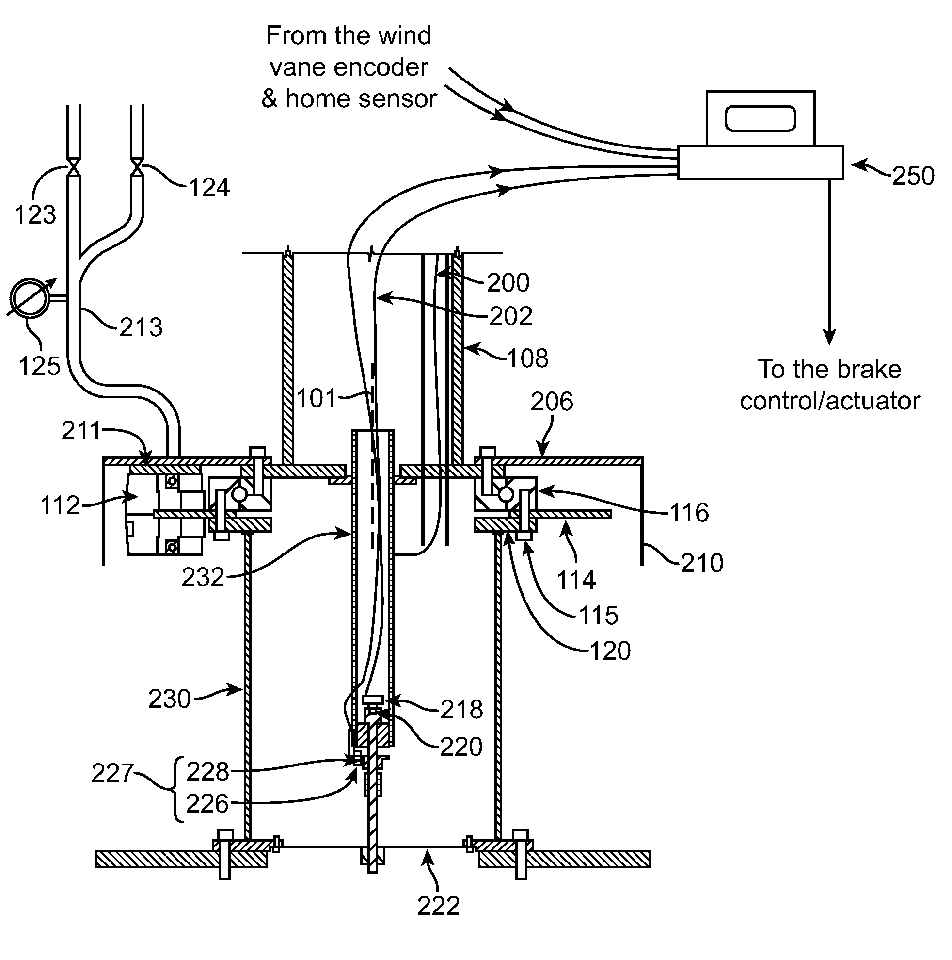
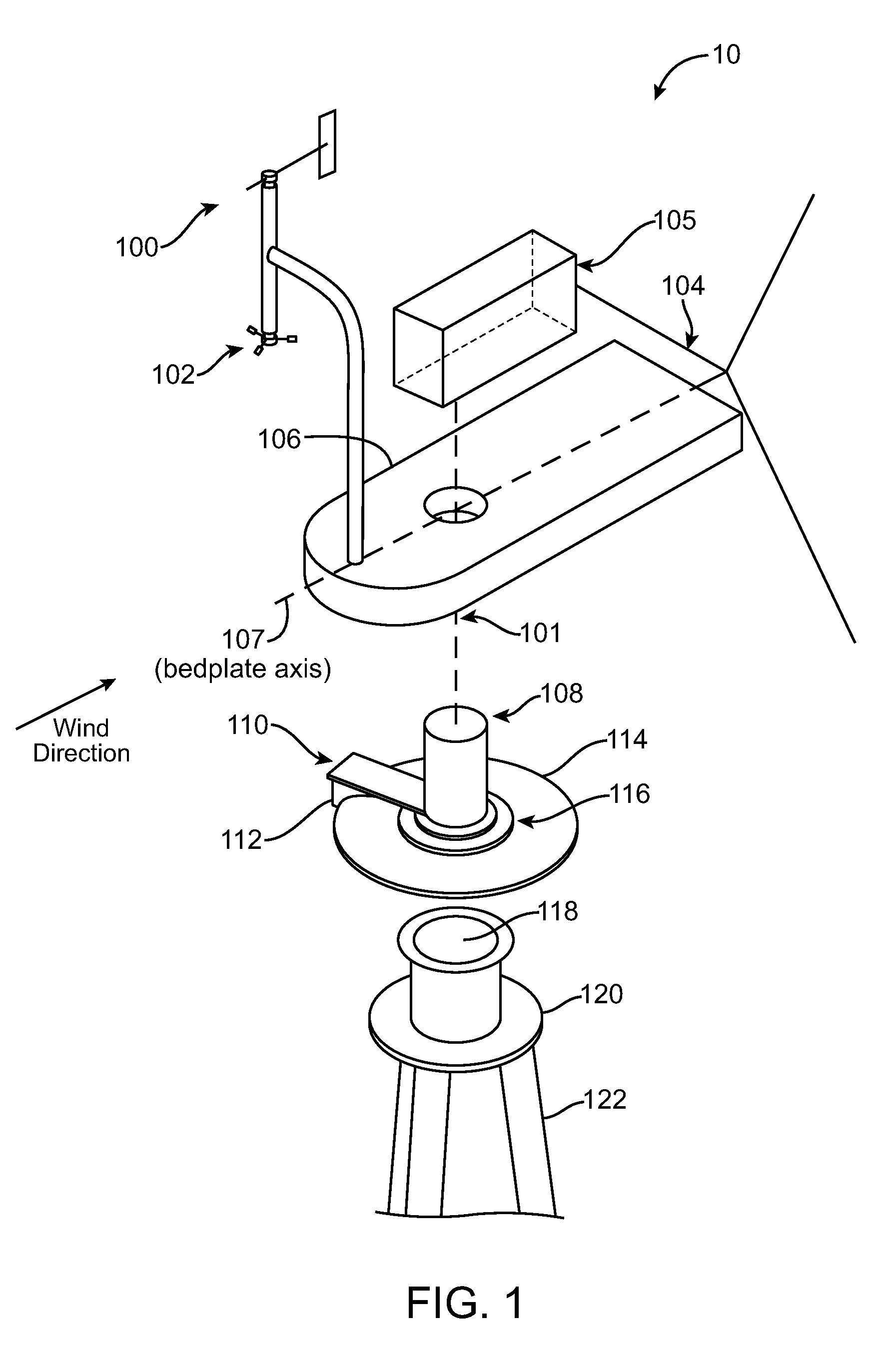
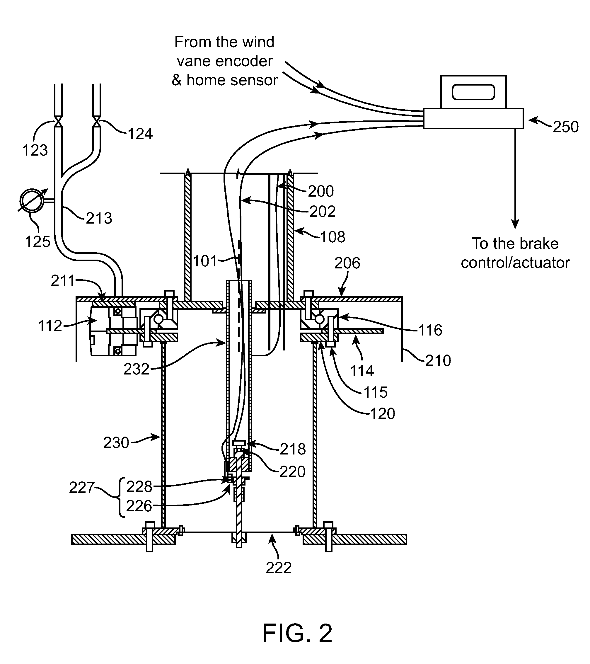
[0030]The present invention relates to systems for wind turbine yaw control. A wind turbine bedplate is rotateably mounted on a stationary tower. The bedplate is connected to a yaw encoder, which provides angular position of the bedplate with respect to the stationary tower. A wind vane, which can be attached to the bedplate, is connected to a wind vane encoder. The yaw encoder and wind vane encoder send data to a turbine controller. When the bedplate orientation differs from the average wind direction by a predetermined amount, a yaw brake that keeps the bedplate in place is released in a controllable fashion, such that some amount of friction between the brake pads and the stationary disk remains. Consequently, the bedplate will controllably rotate to align itself with the newly established average wind vector, thus aligning the turbine blade rotation plane substantially perpendicularly against the average wind vector. When the bedplate arrives to its new position, as determined b...


PUM


Abstract

Apparatuses and methods are disclosed for the wind turbine yaw control. A wind turbine bedplate is rotateably mounted on a stationary tower. The bedplate is connected to a yaw encoder, which provides angular position of the bedplate with respect to the stationary tower. A wind vane, which can be attached to the bedplate, is connected to a wind vane encoder. The yaw encoder and wind vane encoder send data to a turbine controller. When the bedplate orientation differs from the average wind direction by a predetermined amount, a yaw brake that keeps the bedplate in place is released in a controllable fashion, such that some amount of friction between the brake pads and the stationary disk remains. Consequently, the bedplate will controllably rotate to align itself with the newly established average wind vector, thus aligning the turbine blade rotation plane substantially perpendicularly against the average wind vector. When the bedplate arrives to its new position, as determined by the yaw encoder reading, the yaw brake can be fully applied again to fix the bedplate at its new position.

Description

BACKGROUND OF THE INVENTION[0001]This application claims priority to the provisional U.S. Patent Applications No. 61 / 152,526, filed Feb. 13, 2009, which is incorporated herein by reference in its entirety.[0002]The present invention relates generally to wind turbines. More particularly, the present invention relates to the yaw angle adjustment systems and methods. These systems and methods adjust the turbine yaw angle with respect to the incoming wind in order to optimize power production by the turbine.[0003]Due to the concerns over global warming and limited amount of fossil fuels, alternative methods of energy production are desired. One such alternative source of energy is the wind energy produced by wind turbines, which convert kinetic energy of the wind into electricity. The performance of a wind turbine is determined by many factors: size of the turbine blades, wind speed, type of the turbine (upwind or downwind), electrical generator's converting efficiency, and the orientat...

Claims


Application Information

Patent Timeline
Patent Type & Authority Applications(United States)
IPC IPC(8): F03D7/04
CPCF03D7/0204F03D7/0212F03D7/0248F03D7/042Y02E10/723F05B2270/321F05B2270/329F05B2270/809F05B2270/107Y02E10/72
Inventor MIGLIORI, ROBERT
Owner MIGLIORI ROBERT
Why Eureka
Try Eureka