Pipette Device and Method of Manufacture and Use Thereof

a pipette and pipette technology, applied in the field of pipette devices and methods, can solve the problems of reducing the sensitivity of pressure control of pipette, difficult observation and control of cell movement, and not being suitable for some non-quantitative fluid transfer

Inactive Publication Date: 2010-08-19
TAO JUN
View PDF3 Cites 11 Cited by
  • Summary
  • Abstract
  • Description
  • Claims
  • Application Information

AI Technical Summary

Benefits of technology

[0019]Moreover, the present invention provides a pipette device comprising a lever (also referred to herein as an “actuating mechanism”) that can be a screw-type with a knob attached to the proximal end of the pipette controller of the pipette device and is capable of rotating a rod having threads and contained inside of the pipette controller to create positive or negative air pressure at the distal end of the rigid tube. Alternatively, the lever or actuating mechanism can be a piston-type with a plunger capable of moving back and forth inside the pipette controller to engage positive or negative air pressure at the distal end of the rigid tube. In the piston-type embodiments, the plunger is controlled by a spring and a thumb rest, and the pipette device further comprises a sealer to prevent air leaking around or between the plunger and the pipette controller. In certain piston-type embodiments, the pipette device further comprises an element between the spring and the sealer to further adjust the pressure created by the spring by passing the pressure to the sealer. The element further comprises an aspect in the middle to allow the plunger to move back and forth through the part easily. In certain embodiments, the aspect is a V-shaped hole with the larger surface face to the spring, allowing the plunger to move in.

Problems solved by technology

A conical shaped pipette tip, in which a pipette tip is capped to the distal end of a pipette, is often applied to volumetric pipettes or graduated pipettes, but not suitable for some non-quantitative fluid transfer, especially when the purpose is to transfer cells or oocyte / embryos.
Using a conical shaped pipette tip makes the observation and control of cell movement difficult.
A conical shaped pipette tip has a large internal air space that reduces the sensitivity of pressure control by a pipette.
The problems of using a continuously constant inner diameter pipette tip, for which one first has to insert a metal plunger into a pipette tip, then push the pipette tip through a rubber sealer, and finally tighten a collet, include: (1) loading and unloading a pipette tip can be over elaborate, complicated, and involves several steps as described above; (2) inserting a metal plunger into different pipette tips increases the possibility of cross contamination; (3) a pipette tip made from glass may easily break during loading / unloading and tightening of a collet; and (4) because a plunger moves back and forth inside a pipette tip, the pipette tip has to be made to have a sufficient length, which can be inconvenient or difficult to use.
The consequence is that the retained cells or embryos are at high risk of exposure to a non-optimal temperature and that the medium pH may quickly change to an unacceptable level.
Quickly rescuing the retained cells or embryos becomes a challenge.
However, pulling the micropipette tip may create more negative force inside the pipette tip, which causes the cells or embryos to be sucked deeper into the tip.
In addition, even if the tip is successfully removed from the dysfunctional micropipette controller, loading the pipette tip (that has retained cells or embryos) to a functional controller presents another challenge.
Thus, the increased pressure expels the retained cells or embryos from the tip resulting in cell and embryo loss.
Cells or embryos are at a very high risk of getting lost during this process.
When loading the micropipette tip back to the micropipette controller after adjusting the controller, a positive pressure is created that can expel the cells or embryos, which results in lost cells or embryos.
The challenge is that, after aspirating cells or embryos into the unit, the unit has to be unloaded from a micropipette controller and a negative pressure is created during the unloading process.
These increased or decreased air pressures created inside the unit may shift cell or embryo to an undesirable position inside the pipette tip and even causes loss of cells or embryos.

Method used


Image

  • Pipette Device and Method of Manufacture and Use Thereof
  • Pipette Device and Method of Manufacture and Use Thereof
  • Pipette Device and Method of Manufacture and Use Thereof

Examples


Embodiment Construction

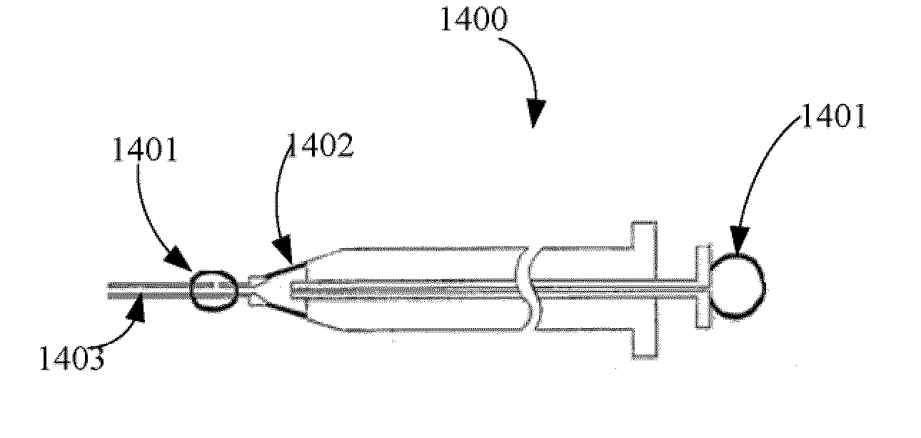
[0038]Embodiments of the present invention provide a pipette device for moving or transferring micron quantities of fluid (such as about 3-5 micron, or as low as less than 1 micron) including its contents, such as cells and oocytes / embryos, with a simplified pipette tip loading and unloading process. Embodiments of the present invention further provide a pipette device comprising a pipette controller by which air pressure inside and outside of the micropipette controller can be intentionally balanced.

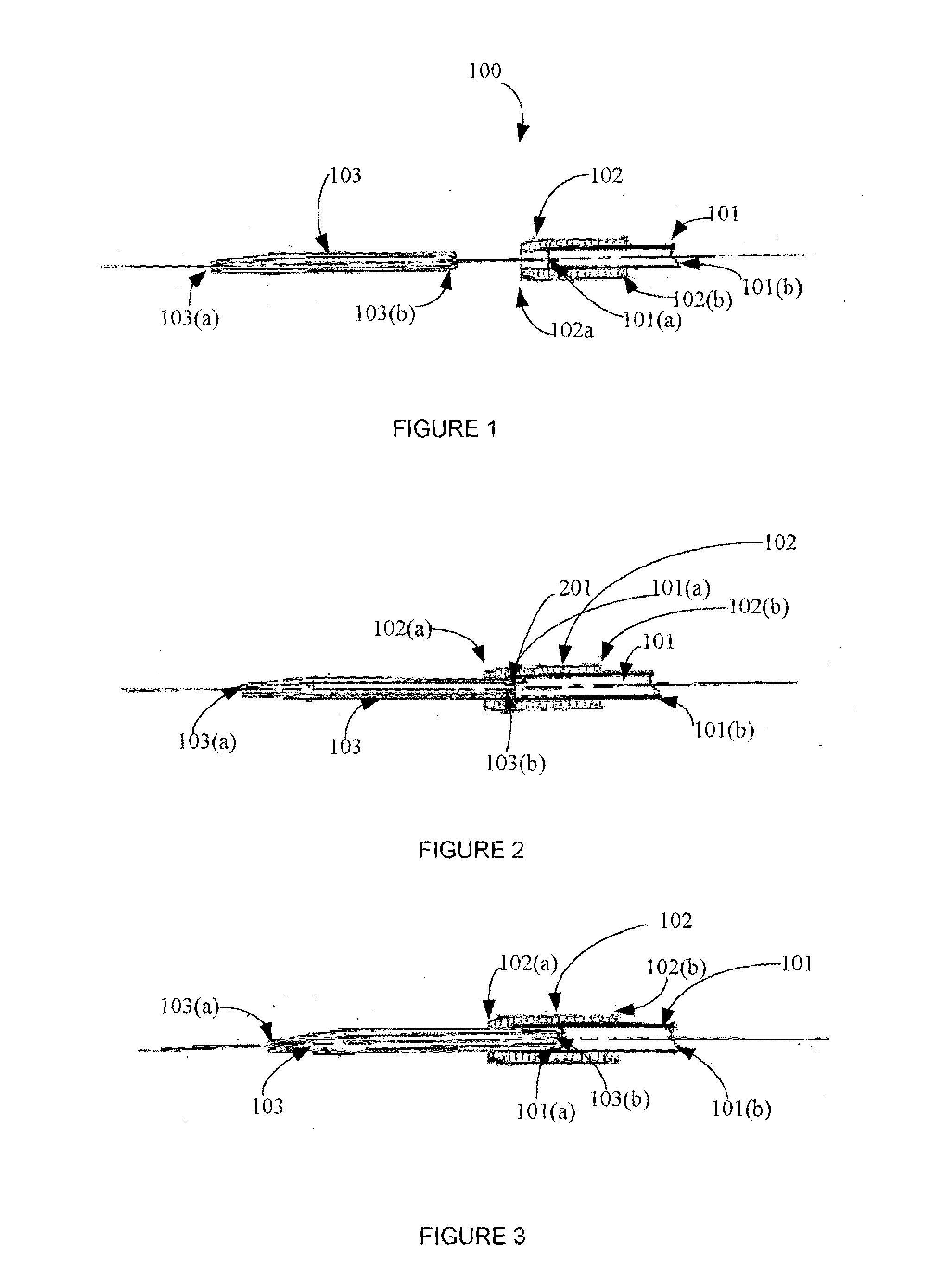
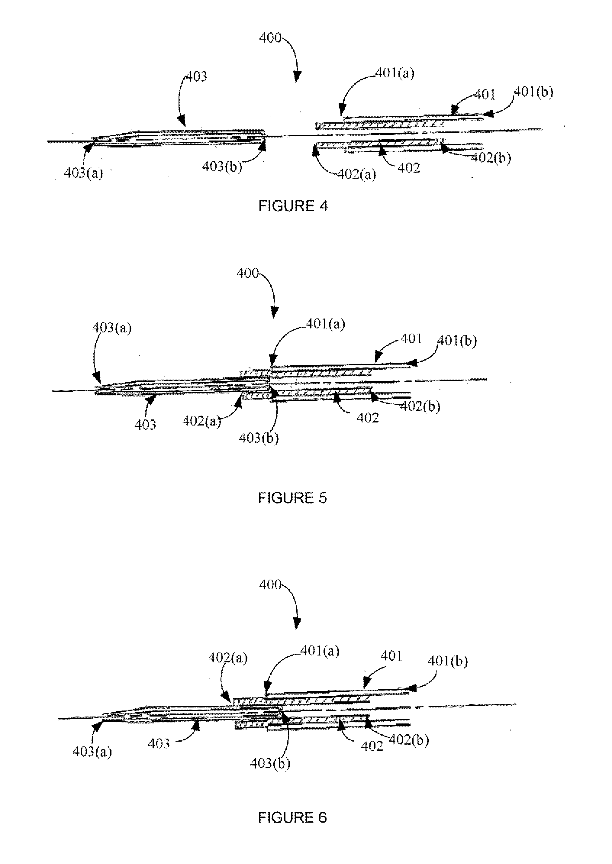
[0039]In certain embodiments, the present invention provides a pipette device comprising: a) a pipette controller having a proximal end, a distal end, a rigid tube extending from the distal end, and a manually engageable lever or actuating mechanism for creating positive and negative air pressure at the distal end of the rigid tube, b) a flexible sealing tube having a proximal end and a distal end, wherein the proximal end of the sealing tube creates an externally air-tight seal in comm...


PUM

PropertyMeasurementUnit
lengthaaaaaaaaaa
lengthaaaaaaaaaa
lengthaaaaaaaaaa

Abstract

The present invention provides a pipette device for moving or transferring micron quantities of fluid and cells, particularly oocytes/embryos, with a simplified pipette tip loading and unloading process. The present invention further provides a pipette device comprising a controller by which air pressure inside and outside of the controller can be intentionally balanced. Methods of manufacture and use of the pipette device of the present invention are also provided.

Description

CROSS REFERENCE OF RELATED APPLICATIONS[0001]This application claims priority to U.S. Provisional Application Ser. No. 61 / 153,546, entitled “A New Pipette With Easy Disposable Pipette Tip Loading / Unloading,” filed Feb. 18, 2009, and U.S. Provisional Application Ser. No. 61 / 292,077, entitled “Safety Device for Pipette Controllers”, filed Jan. 4, 2010, the entire contents of these two applications are incorporated by reference herewith.FIELD OF THE INVENTION[0002]The present invention relates to a pipette device, and method of manufacture and use thereof, to handle or rescue cells or embryos.BACKGROUND OF THE INVENTION[0003]To precisely and quantitatively transfer small volume of fluid, pipettes are widely applied in routine laboratory practices. Sometimes, non-quantitative fluid transfer is also an important activity when the purpose is to move cells, oocytes or embryos from one culture dish to another, in which the exact liquid volume to be transferred is not very critical but depen...

Claims


Application Information

Patent Timeline
Patent Type & Authority Applications(United States)
IPC IPC(8): B01L3/02B23P11/00
CPCB01L3/021B01L3/0217B01L3/0275Y10T29/49826B01L2300/0838B01L2400/0478B01L2400/0481B01L2200/0689
Inventor TAO, JUN
Owner TAO JUN
Why Eureka
Try Eureka