Coating method, and coating apparatus

Inactive Publication Date: 2010-08-19
KONICA MINOLTA INC
View PDF8 Cites 20 Cited by
  • Summary
  • Abstract
  • Description
  • Claims
  • Application Information

AI Technical Summary

Benefits of technology

[0022]Plural coating solutions such as a coating solution formed from an organic EL material and another coating solution formed from an organic photoelectric conversion element material are possible to be coated onto a support in one pass with no mutual mixture of the coating

Problems solved by technology

However, in the case of the foregoing methods, there appeared problems such as low effi

Method used


Image

  • Coating method, and coating apparatus
  • Coating method, and coating apparatus
  • Coating method, and coating apparatus

Examples


example 1

Support

[0115]A transparent gas barrier film obtained by laminating three layers of a unit possessing a low density layer, a medium density layer, a high density layer and a medium density layer was prepared on a substrate of polyether sulfon (film manufactured by Sumitomo Bakelite Co., Ltd., hereinafter, abbreviated as PES) having a thickness of 200 μm under, employing the following atmospheric plasma discharge treatment apparatus and discharge conditions.

(Atmospheric Plasma Discharge Treatment Apparatus)

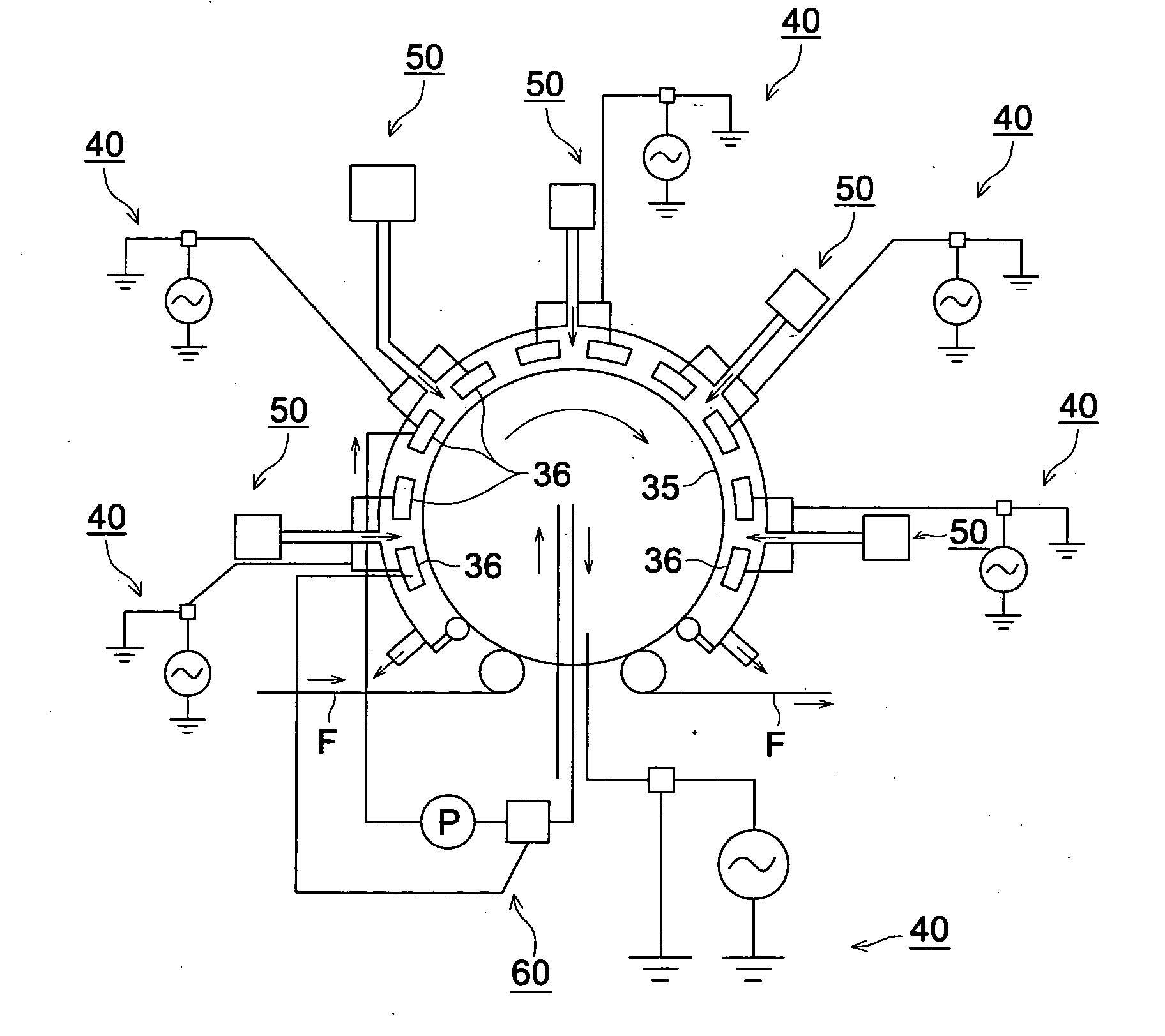
[0116]FIG. 4 is a configuration cross-sectional view of an atmospheric plasma discharge treatment apparatus. The atmospheric plasma discharge treatment apparatus is equipped with roll rotation electrode 35 and plural rectangular tube electrode 36 as facing electrodes, electric field application device 40, gas supply device 50 and electrode temperature adjustment device 60.

[0117]A set of roll rotation electrode 35 covered with a dielectric and plural rectangular tube type electrode 3...

example 2

Support

[0151]The same film as in Example 1 was employed to prepare a transparent gas barrier film by the same method.

>

[0152]After an anode was prepared by the same method as in Example 1, the same surface treatment was carried out

>

[0153]Polyethylenedioxythiphenepolystyrene sulfonate (PEDOT / PSS, Baytron P Al 4083 produced by Bayer AG.) was diluted by 70% with methanol to prepare a hole transport layer coating solution.

>

[0154]Five % by weight of Ir(ppy)3 as a green dopant material was mixed with polyvinyl carbazole (PVK) as a host material, and dissolved in 1,2-dichloroethane. Only the amount of solvent was changed, and a solution having a solid content of 2% by weight was made.

>

[0155]Employing a backup roll having a diameter of 4.5 m, a slot type coater for a hole transport layer, and an inkjet coating apparatus for an emission layer, both solutions for the hole transport layer and the emission layer were coated at a coating speed of 4 m / min so as to give a wet coating layer thicknes...

example 3

Support

[0158]The same film as in Example 1 was employed to prepare a transparent gas barrier film by the same method.

>

[0159]After an anode was prepared by the same method as in Example 1, the same surface treatment was carried out

>

[0160]Polyethylenedioxythiphenepolystyrene sulfonate (PEDOT / PSS, Baytron P Al 4083 produced by Bayer AG.) was diluted by 70% with methanol to prepare a hole transport layer coating solution.

>

[0161]Five % by weight of Ir(ppy)3 as a green dopant material was mixed with polyvinyl carbazole (PVK) as a host material, and dissolved in 1,2-dichloroethane. The amount of solvent was changed, and a solution having a solid content of 3% by weight was made.

>

[0162]Employing a backup roll having a diameter of 1 m, and an inkjet coating apparatus, both solutions for a hole transport layer and an emission layer were coated at a coating speed of 2 m / min so as to give a wet coating layer thickness of the lower layer of 2 μm, and a wet coating layer thickness of the upper la...


PUM


Abstract

The invention provides a coating method by which plural coating solutions of a coating solution formed from organic EL material for formation of an organic EL layer in an organic EL element and another coating solution formed from organic photoelectric conversion element material for formation of an organic photoelectric conversion element layer can be coated to prepare a multilayer film with no damage of the organic EL layer and organic photoelectric conversion element layer, and also provides a coating apparatus with the coating method. It is a feature in the coating method that plural coating units each facing a backup roll and sandwiching a long length support with the backup roll are provided, and plural coating solutions are coated onto the support by the plural coating units to form a multilayer coating film, wherein the moving support is wound up by the continuously moving backup roll supporting the support.

Description

TECHNICAL FIELD[0001]The present invention relates to a coating method to form a multilayer coating film layered on a support by coating plural coating solutions, and a coating apparatus thereof.BACKGROUND[0002]A coating film obtained by coating a functional coating solution (hereinafter, referred to also as a coating solution) is utilized for electrode material for display devices of a liquid crystal display, a plasma display, inorganic electroluminescence and organic electroluminescence (hereinafter, referred to as organic EL), elect ode material for optical elements of light emitting apparatuses fitted with inorganic and organic elements, a touch panel material, and materials for an organic photoelectric conversion element and a solar battery. In the case of the foregoing display devices and optical elements, a glass substrate is mainly employed as a support, but in recent years, the glass substrate has been considered to be replaced by a film substrate because of a trend of use ...

Claims


Application Information

Patent Timeline
IPC IPC(8): B05D1/36B05C5/00
CPCB05C5/0254H01L51/56H01L21/02B05C9/06H10K71/00
Inventor SAKATA, KAZUHIKOENDO, KIYOSHI
Owner KONICA MINOLTA INC
Why Eureka
Try Eureka