Power Storage Device

Active Publication Date: 2010-08-19
SEMICON ENERGY LAB CO LTD
View PDF17 Cites 89 Cited by
  • Summary
  • Abstract
  • Description
  • Claims
  • Application Information

AI Technical Summary

Benefits of technology

[0015]Furthermore, because the insulator is provided over each of the plurality of projections, even when pressure is applied between the positive electrode and the negativ

Problems solved by technology

However, the positive or negative electrode may expand due to charging, and with that pressure, the separator may be broken and defective short circuit may be caused.
In additi

Method used


Image

  • Power Storage Device
  • Power Storage Device
  • Power Storage Device

Examples


Example

Embodiment 1

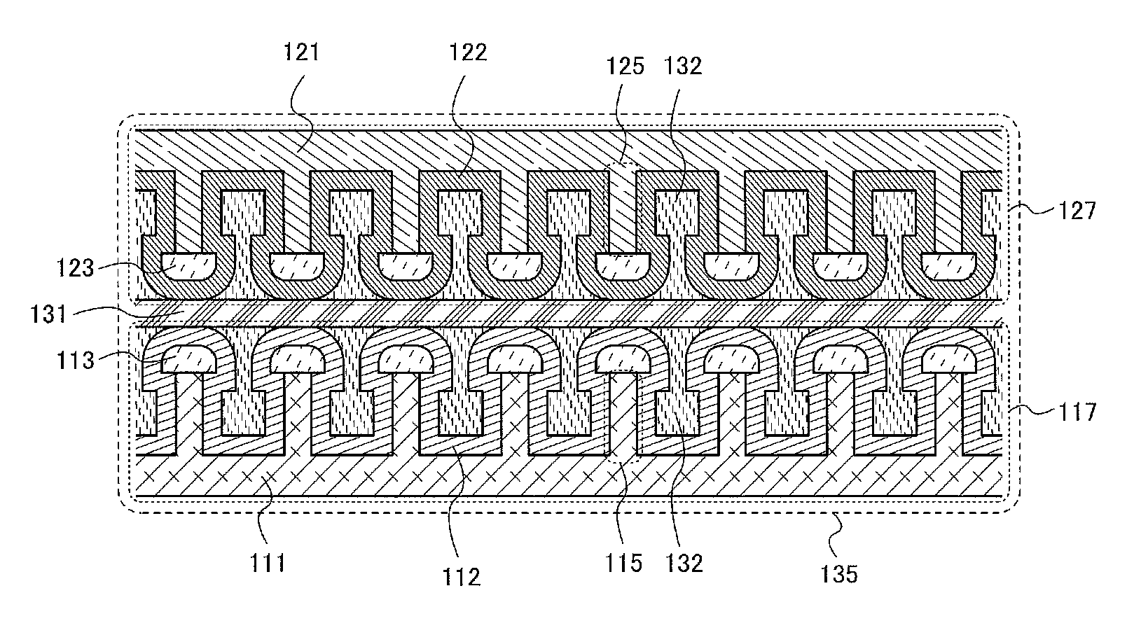
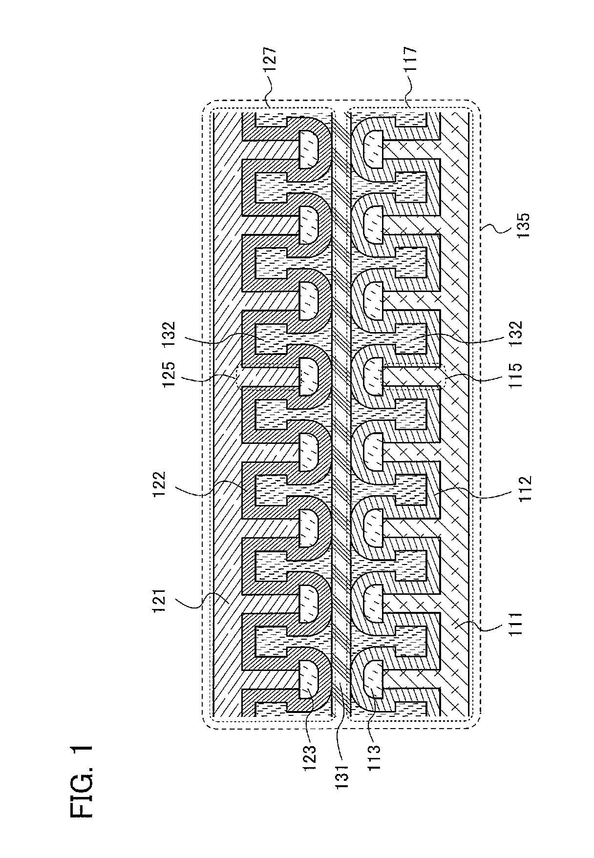
[0021]This embodiment is described with reference to FIG. 1, FIGS. 2A to 2D, FIGS. 3A to 3D, and FIGS. 4A and 4B.

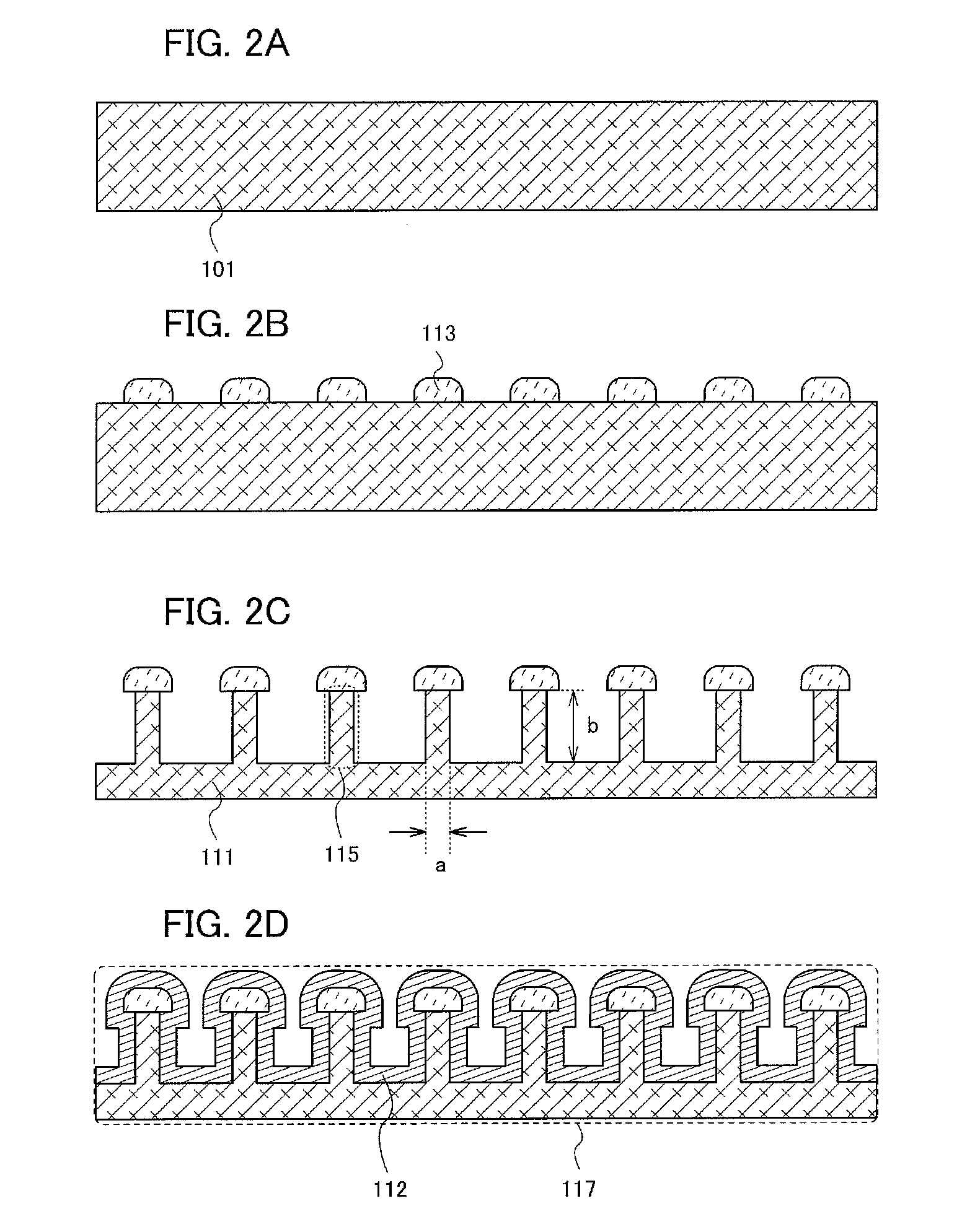
[0022]Over a plate-like positive-electrode material 101 (see FIG. 2A) which is a material of a positive-electrode current collector 111, a plurality of insulators 113 serving as an etching mask are formed (see FIG. 2B).

[0023]As the plate-like positive-electrode material 101, a simple substance, such as aluminum (Al) or titanium (Ti), or a compound thereof may be used.

[0024]Examples of the insulators 113 include organic resins such as an acrylic resin, a polyimide resin, a polyimide amide resin, a phenol resin, and an epoxy resin. The insulators 113 may be formed with such an organic resin by a printing method, a spin-coating method, or the like. For example, the insulators 113 may be formed as follows: unexposed photosensitive acrylic is formed over a surface of the plate-like positive-electrode material 101 by a printing method and regions where the insulator...


PUM


Abstract

An embodiment of the present invention relates to a power storage device which includes a positive electrode having a positive-electrode current collector with a plurality of first projections, a first insulator provided over each of the plurality of first projections, and a positive-electrode active material provided on a surface of the first insulator and the positive-electrode current collector with the plurality of first projections; a negative electrode having a negative-electrode current collector with a plurality of second projections, a second insulator provided over each of the plurality of second projections, and a negative-electrode active material provided on a surface of the second insulator and the negative-electrode current collector with the plurality of second projections; a separator provided between the positive electrode and the negative electrode; and an electrolyte provided in a space between the positive electrode and the negative electrode and containing carrier ions.

Description

BACKGROUND OF THE INVENTION[0001]1. Field of the Invention[0002]The invention disclosed in this specification relates to power storage devices.[0003]2. Description of the Related Art[0004]In recent years, power storage devices, such as lithium-ion secondary batteries, which are secondary batteries where lithium metal oxide is used as a battery material and which are charged and discharged by the movement of lithium ions as carrier ions between a positive electrode and a negative electrode, and lithium-ion capacitors, have been actively developed (see References 1 to 3).REFERENCES [Reference 1] Japanese Published Patent Application No. 200 8-2943 14 [Reference 2] Japanese Published Patent Application No. 2002-289174 [Reference 3] Japanese Published Patent Application No. 2007-299580 SUMMARY OF THE INVENTION[0005]In order to obtain a power storage device with high capacity, the surface areas of a positive electrode and a negative electrode should be increased. The surface areas of ...

Claims


Application Information

Patent Timeline
IPC IPC(8): H01M6/16H01M2/16H01G11/66H01G11/70H01G11/72H01M4/66H01M4/70H01M10/058H01M50/409
CPCH01M2/16H01M4/13H01M4/139H01M4/667H01M4/70Y02E60/13H01M10/0569H01M2300/0045Y02E60/122H01G11/52H01G11/70H01M10/052Y02P70/50Y02E60/10H01M50/409
Inventor YAMAZAKI, SHUNPEIIZUMI, KONAMI
Owner SEMICON ENERGY LAB CO LTD
Why Eureka
Try Eureka