
Radiation detection device

a radiation detection and radiation detection technology, applied in radiation measurement, instruments, electrical equipment, etc., can solve the problems of limited efficiency, low detection efficiency, and low effective thickness of detector materials, so as to improve detection efficiency and increase the effective thickness of detection materials

Inactive Publication Date: 2010-08-26
COMMISSARIAT A LENERGIE ATOMIQUE ET AUX ENERGIES ALTERNATIVES
View PDF8 Cites 3 Cited by
  • Summary
  • Abstract
  • Description
  • Claims
  • Application Information

AI Technical Summary

Benefits of technology

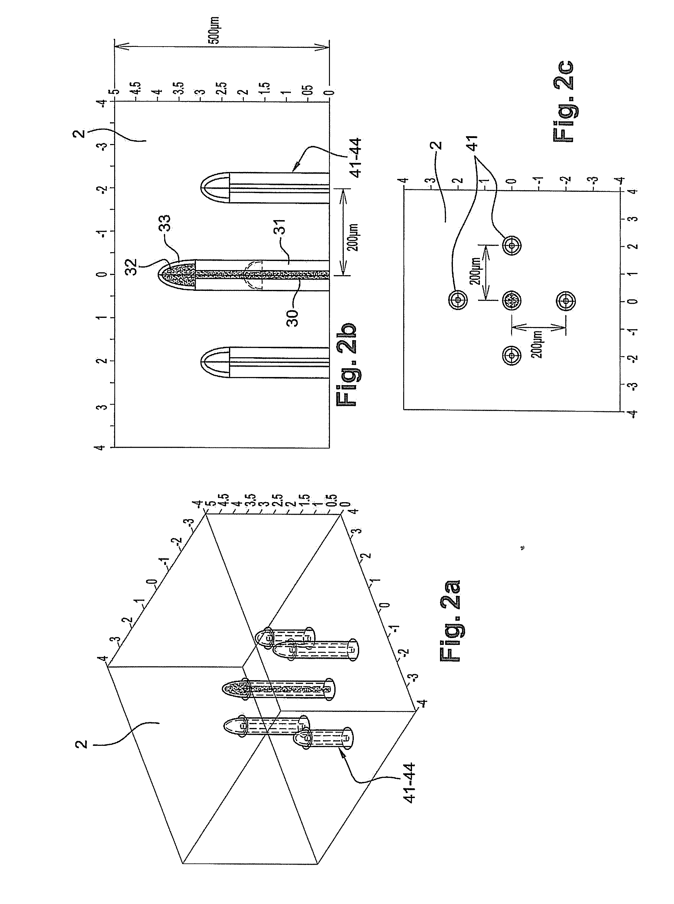
The invention is a device for detecting electromagnetic radiation or charged particles. It includes a detector material that interacts with the radiation to release electron and electron hole mobile charge carriers. The device also includes non-collecting electrodes that are positioned within the detector material and are insulated from it. These electrodes are connected to a prior art measurement device to process the signals collected. The non-collecting electrodes can be arranged parallel to the electric field and have different lengths, or perpendicular to it. The technical effect of the invention is to increase the effective thickness of the detection material to improve detection efficiency.

Problems solved by technology

Some constituent materials of such detectors do not have good charge carrying properties.
As a result, the effective thickness of the detector material is limited by the charge carrying properties of said material.
This efficiency is therefore also limited by the charge carrying properties of the detector material.
However, and as recalled previously, it is known that the mobility, and / or the life cycle of the charge carriers in some detection materials, is low.
Thus, when the interaction of the incident radiation with said detector material occurs beyond a certain distance from the polarization electrodes or collecting electrodes, the charge carriers fail to reach a collecting electrode.
The useful thickness of the detector material, in other words that in which interactions give rise to the genesis of charge carriers collected by a collecting electrode, is therefore limited.
In doing this, the detection efficiency of such a device proves limited.

Method used


Image

  • Radiation detection device
  • Radiation detection device
  • Radiation detection device

Examples


first embodiment

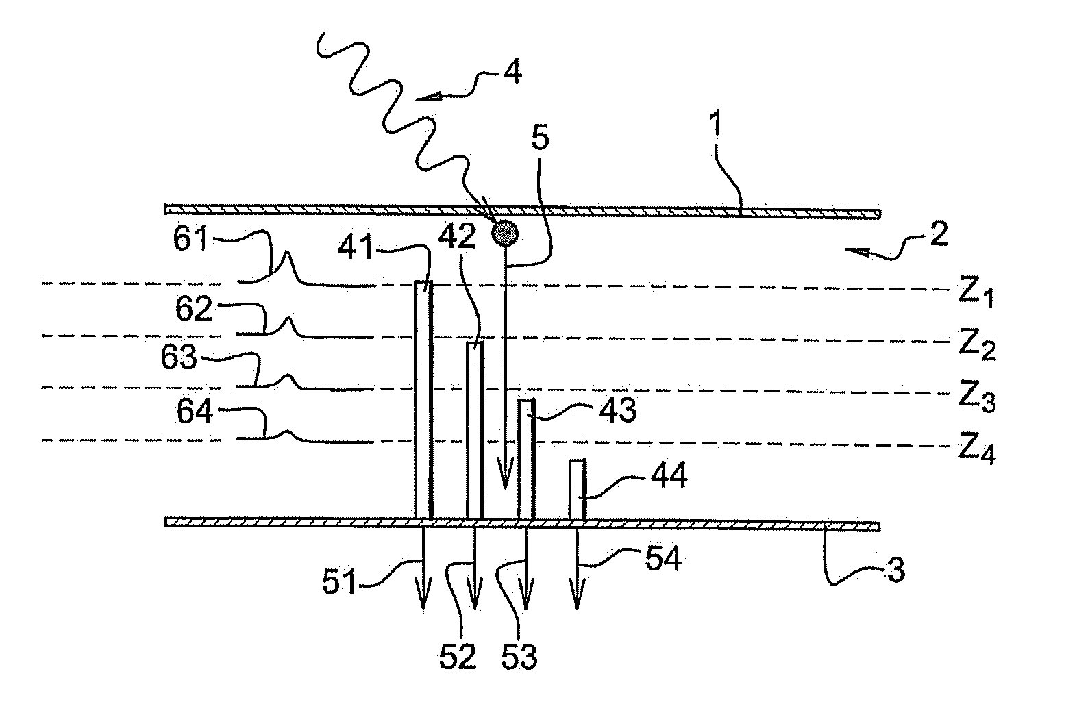
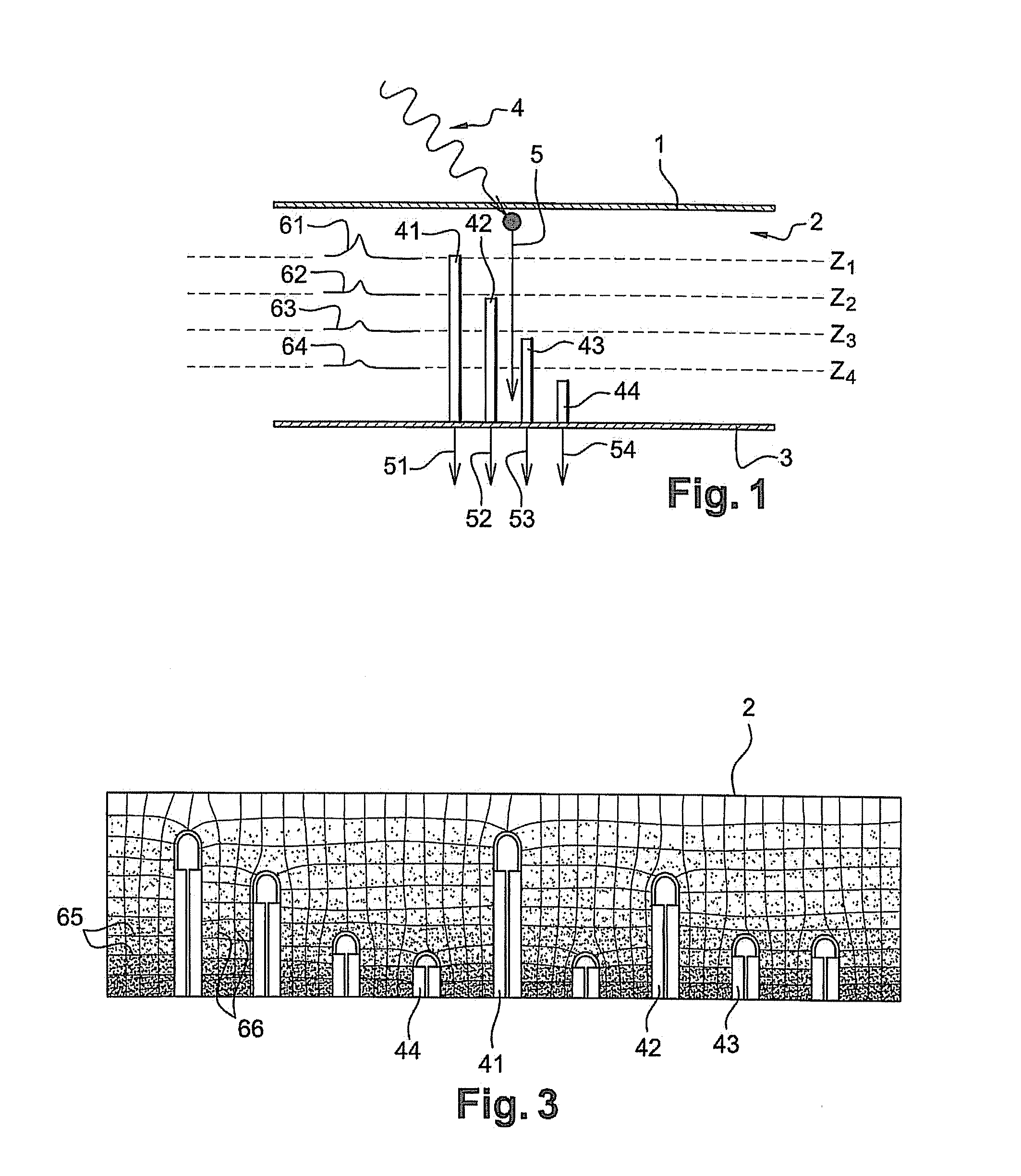
[0036]In FIG. 1 a cross-sectional view of an ionizing radiation detector in accordance with the invention has been shown schematically.

[0037]Basically, this detector includes a stack of a first set of electrodes (1), in the case in point constituted by a unitary cathode, a material sensitive (2) to ionizing radiation, such as for example one made out of an alloy of cadmium, zinc and tellurium (CdZnTe), and a second set of electrodes (3), constituted for example by an anode array. The electrode sets (1) and (3) are polarized so as to create between them, and therefore through the detection material (2), an electric field.

[0038]The material constituting the detector itself (2) may also be made out of semi-conductor material such as Si, GaAs, Ge, InP, CIS, of even of semi-conductor polymers. The thickness of said material is typically between a few hundred micrometers and a few millimeters, or even more than that. As already stated supra, detection efficiency is directly related to the...

second embodiment

[0096]The mode of manufacturing this second embodiment is identical to the previous one, the holes made in the detector material preferentially being through holes.

[0097]Consequently, as may be imagined, implementing the invention means first of all that spatial information about the interaction point is delivered in a straightforward way, and on the other hand that detection materials can be employed that have hitherto been unusable on account of the reduced length of the charge carrying, and are therefore less expensive.

[0098]Simulations have been made allowing the charge induced in a through non-collecting electrode, according to the second embodiment, to be evaluated. Said simulations are shown in relation to FIGS. 9 to 13.

[0099]FIG. 9 shows a solid detector, in which can be distinguished the polarization electrodes (cathodes and anodes), and a non-collecting electrode (70), arranged perpendicular to the electric field resulting from the polarization. Said non-collecting electro...


PUM


Abstract

This device for the detection of ionizing radiation includes a stack integrating a first set of electrodes (1), a solid detector material sensitive to ionizing radiation (2), capable of interacting therewith by releasing electron and electron hole mobile charge carriers, and a second set of electrodes (3), said first and second sets of electrodes being polarized in such a way that an electric field is applied through the detector material (2), thereby allowing the charge carriers generated by the interaction between the detector material and the ionizing radiation to migrate. It further includes electrically insulated electrodes (41-44), known as non-collecting electrodes, and positioned in the volume of the detector material (2) subjected to the electric field, and capable, by capacitive effect, of detecting the charges induced by the migration of the charge carriers in the volume of the detector subjected to the electric field.

Description

TECHNICAL FIELD[0001]The present invention relates to a device for the detection of ionizing radiation, particularly where this means charged particles or electromagnetic waves. Such a device is commonly used, first of all and with the prime aim of detecting said type of waves and particles for scientific or medical purposes in particular, and then to form images of some parts of an object from the rays transmitted through or diffused or diffracted by said object after irradiation, in order for example to analyze the chemical composition of said object. Another aim of this device is to make images or take measurements by spectrometry.PRIOR ART[0002]To form images, there is a known technique, particularly in the field of X- or gamma ray imaging, of using a parallelepiped detection device with two main directions, generally of the matrix type. The two main directions conventionally define a detection plane, in which the detector can be used to locate the point at which the incident ra...

Claims


Application Information

Patent Timeline
Patent Type & Authority Applications(United States)
IPC IPC(8): G01T1/24
CPCG01T1/241G01T1/2928
Inventor GROS D'AILLON, ERICRUAT, MARIEVERGER, LOICK
Owner COMMISSARIAT A LENERGIE ATOMIQUE ET AUX ENERGIES ALTERNATIVES
Learn More