Magnetic flux controllable rotating electric machine system

a technology of magnetic flux and rotating electric machines, which is applied in the direction of electronic commutators, dynamo-electric converter control, circuit shape/form/construction, etc., can solve the problems of difficult control of electric motors, high-speed rotational regions, and inability to achieve optimal power in a wide rotational speed range, so as to increase the amount of increase the magnetic flux crossing the armature coil, and increase the magnetic resistance

Inactive Publication Date: 2010-08-26
KURA LAB
View PDF8 Cites 52 Cited by
  • Summary
  • Abstract
  • Description
  • Claims
  • Application Information

AI Technical Summary

Benefits of technology

[0021]The field magnet is composed of parallel connection of magnet elements which are different in easiness of magnetization, or includes a permanent magnet whose easiness of magnetization (that is the product of length and coercivity) changes continuously within section thereof. Since magneto-motive force (difference in magnetic potential) is added by the excitation coil to the magnet elements substantially uniformly, the difference in magnetic potential divided by the length becomes strength of magnetic field to be applied to each magnet element, the magnet element with small product of the length and the coercivity is magnetized easily. Therefore, magnetization state of the magnet element which are different in easiness of magnetization is controlled selectively in accordance with the electric current fed to the excitation coil.
[0022]The magnet element has magnetization of one of the first magnetization and the second magnetization which are opposite in direction to each other. The magnet element that magnetizes the magnetic salient poles in the direction opposite to the magnetization direction of the island-shaped magnetic poles is assumed to be the first magnetization, and the amount of magnetic flux crossing the armature coil increases. Therefor, when magnetic pole area of the first magnetization is increased, magnetic flux crossing the armature coil will be increased.
[0023]Magnetic member to connect magnet elements in parallel is desirable to have magnetic saturation flux density almost equal to that of the magnet elements. Otherwise, magnetic flux coming from bigger thickness magnet element may concentrate on smaller thickness magnet element, and smaller thickness magnet element may be demagnetized. When magnetic flux is concentrated beyond saturation flux density, magnetic resistance becomes big, and magnetic flux concentration will be avoided.
[0024]As the magnetic flux induced by the armature coils returns through the armature and neighborhood of the rotor surface, but will not flow through the field magnet, the field magnet is arranged away from the armature coils. Therefor the field magnet is hard to be affected by the armature coils, a low coercivity magnet, or a magnet having small thickness can be applied for the field magnet, and magnetization state of the field magnet is easily controlled. In case that the armature coils are wound around magnetic teeth, distribution of the magnetic flux induced by the armature coils is further localized, and impact on the field magnet is made small.

Problems solved by technology

However, in both electric motors and electric generators, optimum power is not always obtained in a wide rotational speed range because the amount of magnetic flux supplied from field magnet is constant.
In the case of the electric motor, it will become difficult to control the electric motor in a high-speed rotational region because the back electromotive force (power generation voltage) becomes too high, and therefore, various methods for weakening the field strength as field-weakening control have been proposed.
In the case of electric motor, field-weakening control by means of phase leading electric current control has been widely adopted, but the energy efficiency and the control range are limited.
However, this has drawbacks such as that the field magnet is susceptible to the magnetic field of an armature coils, configuration thereof is complicated because an excitation coil and the armature coil interfere with each other, and application is limited to short shaft electric rotational machines because magnetic flux from the field magnet concentrate in the central area.
Therefore a torque change, waveform distortion of the generation voltage are not negligible, and a range of the amount of flux control is limited.
In addition, in any configuration above, half of the rotor surface is covered by permanent magnets, so the reluctance torque is difficult to be exploited.

Method used


Image

  • Magnetic flux controllable rotating electric machine system
  • Magnetic flux controllable rotating electric machine system
  • Magnetic flux controllable rotating electric machine system

Examples


second embodiment

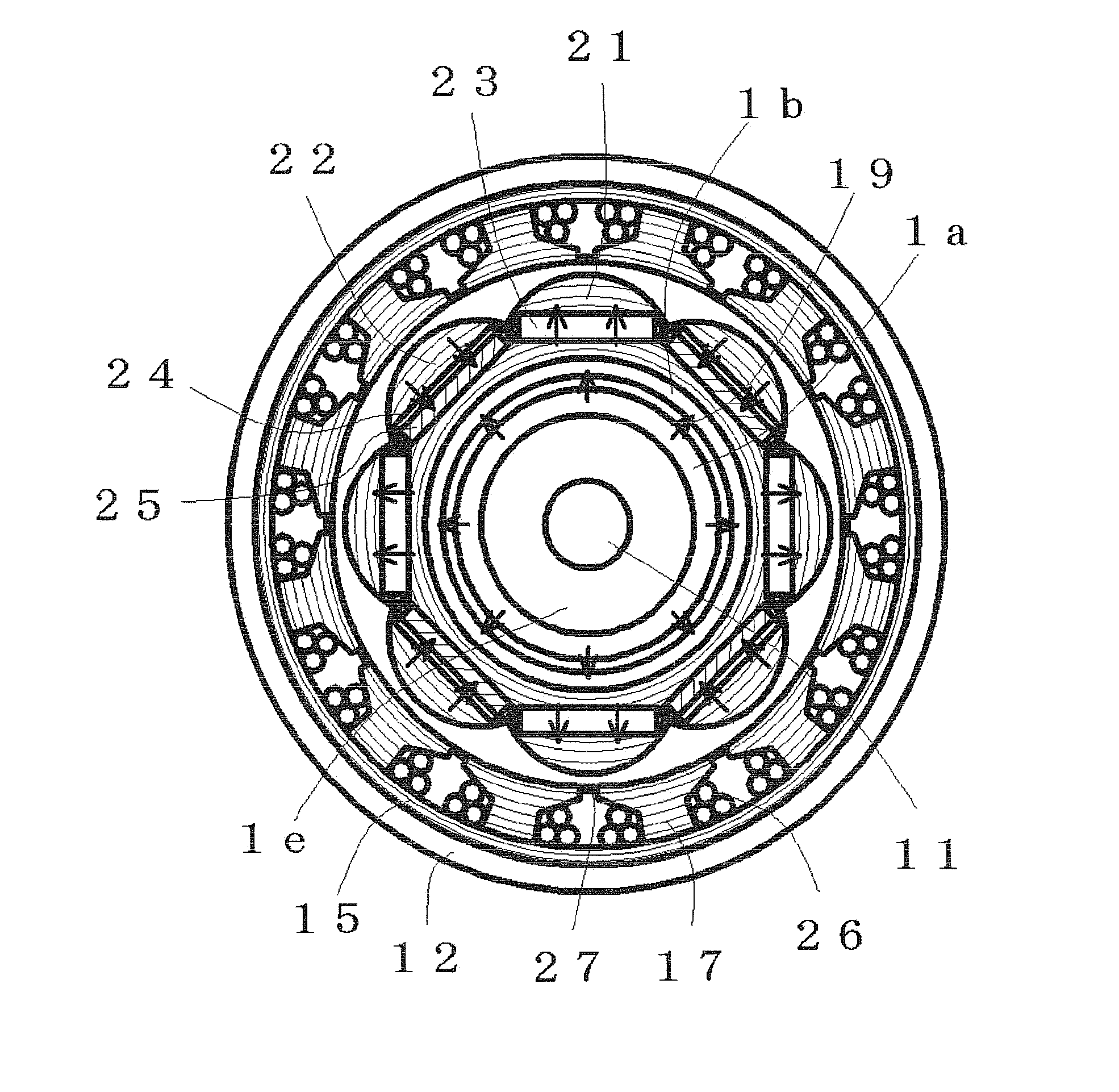
[0123]FIG. 11 illustrates a sectional view of the armature and the rotor along C-C′ of FIG. 10, and some of component parts are appended with numbers for explaining the reciprocal relation. Since an armature composition is the same as the armature composition of the second embodiment, explanation is omitted. The surface magnetic pole part 102 has composition that the cylindrical magnetic substrate is sectioned by permanent magnet assemblies in a circumferential direction. A combination of an intermediate magnetic salient pole 113 and permanent magnet plates 115, 116 having same magnetization direction disposed at both sides of the intermediate magnetic salient pole 113 serves as the permanent magnet assembly. The surface magnetic pole part 102 is characterized in that a uniform magnetic material is partitioned into the island-shaped magnetic poles 111, the magnetic salient poles 112 by the permanent magnet assemblies in the circumferential direction. And each magnetization direction...

first embodiment

[0149]As mentioned above, the rotating electric machine by this embodiment controls flux amount flowing through the armature by changing magnetization state of the field magnet and also the sub-field magnets. Although, flux amount and direction from the magnetic excitation part are controlled by changing magnetization state of the field magnet 13c, composition of the field magnet 13c is same composition as the Further explanation of flux amount control by the magnetic excitation part will be omitted.

[0150]The rotating electric machine system according to a fifth embodiment of the present invention will be explained by using FIG. 18. The fifth embodiment is a rotating electric machine system that a magnetic excitation part does not have a field magnet and controls flux amount flowing through an armature by an electric current.

[0151]FIG. 18 shows a longitudinal sectional view of a rotating electric machine apparatus that the magnetic excitation part of the fourth embodiment is change...


PUM


Abstract

In a magnet-exciting rotating electric machine system, a rotor surface has magnetic salient poles and island-shaped magnetic poles alternately in circumferential direction, and the island-shaped magnetic poles are constituted so that magnetic flux coming from an external source does not flow through. A magnetic excitation part magnetizes the island-shaped magnetic poles and the magnetic salient poles collectively in the same direction, and then control a flux amount flowing through an armature. The armature has armature coils that face the magnetic salient pole and the island-shaped magnetic pole simultaneously so that driving torque fluctuation or power generation voltage waveform distortion is controlled. The magnetic excitation part changes magnetization state of a field magnet irreversibly, or changes an excitation current to an excitation coil to control a flux crossing the armature.

Description

CROSS-REFERENCE TO RELATED APPLICATIONS[0001]The present application claims priority under 35 U.S.C. §119 to Japanese Patent Applications No. 2009-40869 filed Feb. 24, 2009, No. 2009-109082 filed Apr. 28, 2009, and No. 2009-196673 filed Aug. 27, 2009. The contents of these applications are incorporated herein by reference in their entirety.BACKGROUND OF THE INVENTION[0002]1. Field of the Invention[0003]The present invention relates to rotating electric machines such as electric generators and electric motors having a permanent magnet.[0004]2. Discussion of the Background[0005]Rotating electric machine apparatus, such as an electric generator for electromagnetically generating electric power by relative rotation of a permanent magnet and an armature, or an electric motor for generating relative rotation between a permanent magnet and an armature by interaction of the permanent magnet and a magnetic field generated by electric current supplied to the armature, are excellent in energy ...

Claims


Application Information

Patent Timeline
Patent Type & Authority Applications(United States)
IPC IPC(8): H02P6/14H02K21/14
CPCH02K1/276H02K1/2766H02K21/046H02K21/12Y02T10/641B60L11/123Y02T10/7077Y02T10/7005Y02T10/6217H02K21/38B60L50/61Y02T10/62Y02T10/64Y02T10/70H02K1/18H02K1/22H02K1/27H02K21/04Y02T10/7072
Inventor ICHIYAMA, YOSHIKAZU
Owner KURA LAB
Why Eureka
Try Eureka