Method for manufacturing connected sheet material, connected sheet material and method for manufacturing optical display unit

a technology of connected sheets and manufacturing methods, applied in the direction of packaging, lamination, decorative surface effects, etc., can solve the problem of only being able to peel off the separator

Active Publication Date: 2010-08-26
NITTO DENKO CORP
View PDF7 Cites 8 Cited by
  • Summary
  • Abstract
  • Description
  • Claims
  • Application Information

AI Technical Summary

Benefits of technology

[0038]In the defect inspection, any defect in the optical film can be inspected, regardless of whether the release film has any defect such as retardation existing in the release film and foreign matter or scratches adhering to or existing in the release film. The release film to be attached again to the sheet product may be a used or new one. In order that the release film to be attached ag...

Problems solved by technology

However, when the end portions are layered and connected as...

Method used


Image

  • Method for manufacturing connected sheet material, connected sheet material and method for manufacturing optical display unit
  • Method for manufacturing connected sheet material, connected sheet material and method for manufacturing optical display unit
  • Method for manufacturing connected sheet material, connected sheet material and method for manufacturing optical display unit

Examples


example 1

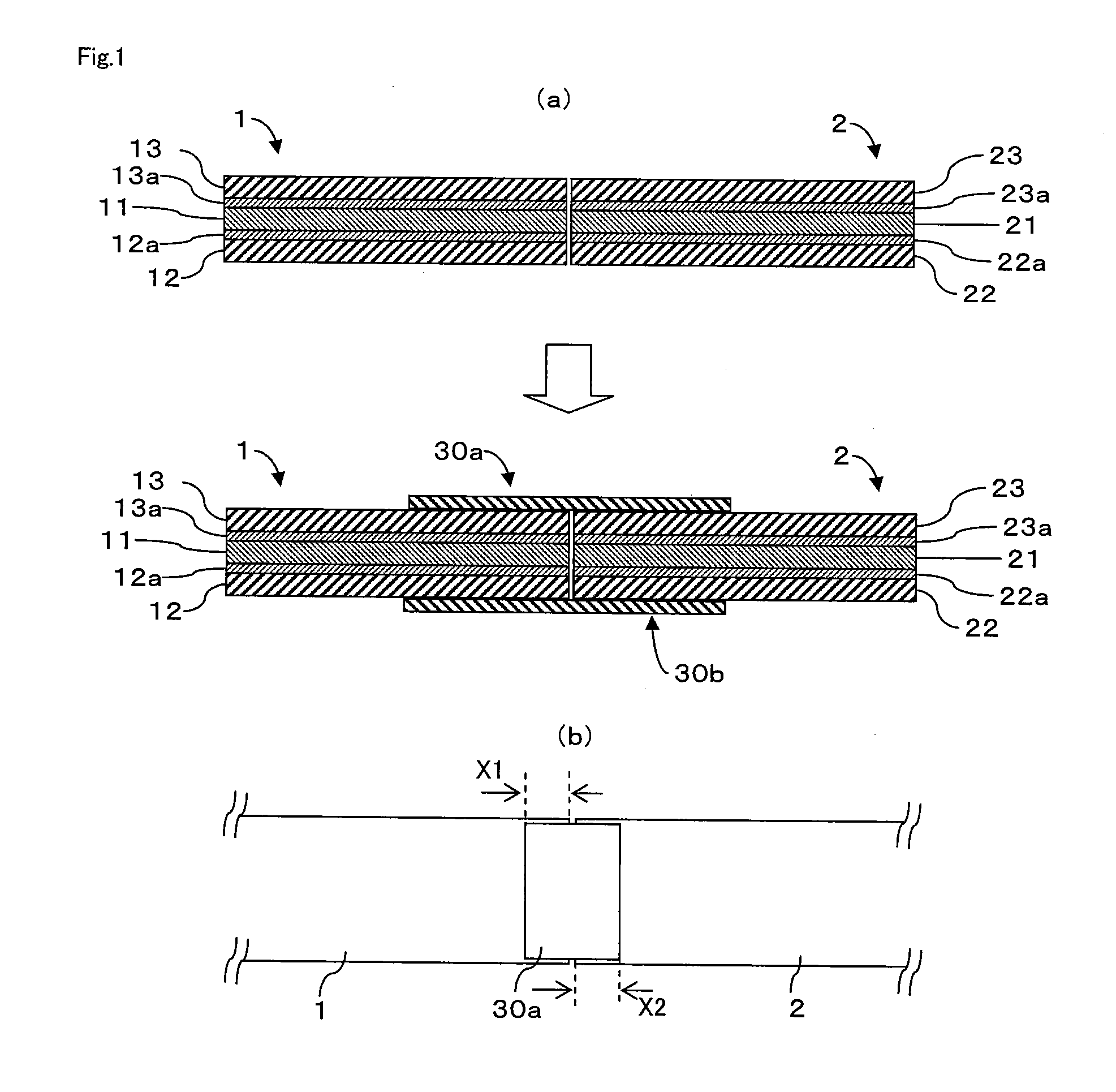
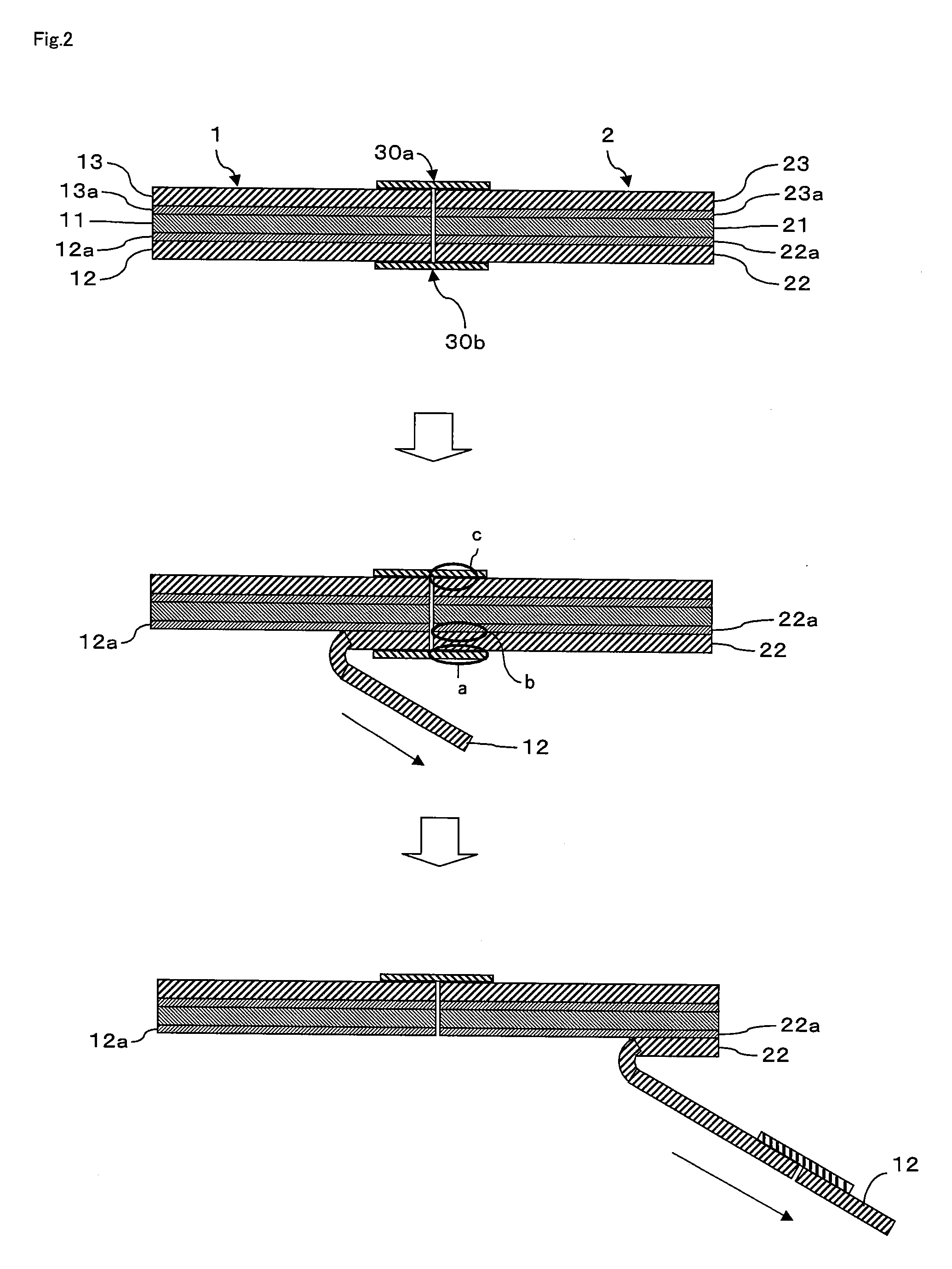
[0101]A connected sheet product and an optical display unit were manufactured using the above connecting method. The sheet product is a laminated structure composed of a surface protecting film (PET film), an acrylic pressure-sensitive adhesive layer, a polarizing plate, an acrylic pressure-sensitive adhesive layer, and a release film (a PET film having a silicone-treated surface to be laminated). The polarizing plate includes a stretched and dyed polyvinyl alcohol film polarizer and triacetylcellulose films provided on both sides of the polarizer with an adhesive interposed therebetween. The connecting member used is an adhesive tape (Dunplon Tape No. 3041 manufactured by Nitto Denko Corporation). The adhesive tape has a width of 10 cm, a thickness of 70 μm, an adhesive strength of 7 N / 25 mm, a tensile strength of 120 N / 25 mm, and an elongation percentage of 140%. Various test methods are the same as those described above. As shown in FIG. 1, the sheet products were connected to ea...

example 2

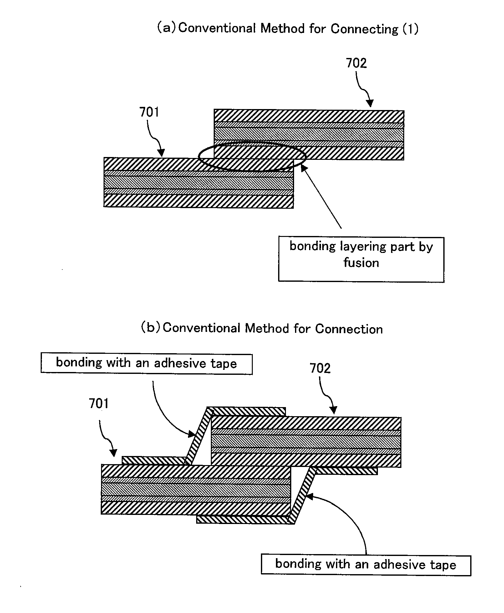
[0102]The connecting method of Example 2 is shown in FIG. 3. The structure of the sheet product is the same as in Example 1. The end faces of the first and second sheet products were opposed to each other, and a heat sealing tool was pressed against both surfaces of the portion where the sheet products were opposed to each other, so that the surface portions 501 and 502 of the sheets in contact with the tool were each subjected to heat fusion. The tool was then removed, and each thermally-fused portion was solidified, so that the sheets were connected to each other. In the resulting connected sheet product, the two sheet products were successfully connected without breaking at the connected portion, although the mechanical strength of the connected portion was slightly lower than that in Example 1. The release films were smoothly and successfully peeled off without interference with the other constituent members, and the resulting sheet product was successfully bonded to a liquid cr...


PUM

PropertyMeasurementUnit
Pressureaaaaaaaaaa
Sizeaaaaaaaaaa

Abstract

The invention is to provide a process for production of a connected sheet product, which makes it possible to connect opposed end faces of two or more sheet products. A process for production of a connected sheet product including sheet products that are connected to one another and each have at least an optical member and a release film provided on one side of the optical member with a pressure-sensitive adhesive interposed therebetween, comprising: opposing a transverse end face of a first sheet product to a transverse end face of a second sheet product; connecting release films of the first and second sheet products with a connecting member (30a); and connecting surface members of the first and second sheet products with a connecting member (30b) on the opposite side from the release films.

Description

TECHNICAL FIELD[0001]The invention relates to a process for production of a connected sheet product by connecting the end faces of sheet products to each other, and to such a connected sheet product. The invention also relates to a process for production of an optical display unit with such a connected sheet product.BACKGROUND ART[0002]A description is given below of a manufacturing method including bonding an optical film to an optical display unit (such as a glass substrate unit in which a liquid crystal is sealed). First, a material roll of a long sheet product including an optical film member is manufactured. For example, the “long sheet product” includes a raw material for a polarizing plate for use in a liquid crystal display. For example, a roll of a raw material for a polarizing plate is manufactured by the process described below. The upstream process includes (A) the step of obtaining a polarizer; (B) the step of manufacturing a polarizing plate, which includes placing a p...

Claims


Application Information

Patent Timeline
IPC IPC(8): B32B33/00B32B37/00B32B38/04
CPCB29C65/02B29C66/83413B29C65/5042B29C66/1122B29C66/1142B29C66/43B29C66/723B29K2029/00B29K2105/24B29K2995/0034B29L2009/00G02B1/105G02B5/3033G02B5/3083G02F1/133528B29C65/18Y10T428/1476Y10T156/1062Y10T156/1082B29C65/5021B29C65/5028B29C65/5092B29C65/4825B29C65/483Y10T156/10Y10T156/1064Y10T156/1075B29C65/00B29C66/73921B29C66/72328B29C66/72321B29C66/71G02B1/14B29K2083/00B29K2081/06B29K2079/08B29K2077/00B29K2075/00B29K2069/00B29K2067/00B29K2063/00B29K2033/12B29K2033/08B29K2029/04B29K2025/06B29K2023/38B29K2023/00B29K2001/00
Inventor KITADA, KAZUOYOKOUCHI, TADASHIAMANO, TAKAICHIYURA, TOMOKAZU
Owner NITTO DENKO CORP
Why Eureka
Try Eureka