Hydraulic system of a gear box

a hydraulic system and gear box technology, applied in the direction of machines/engines, mechanical equipment, positive displacement liquid engines, etc., can solve the problems of large power loss, disadvantageous increase in operating temperature of operating medium, pressure previously produced, etc., and achieve the effect of fuel saving

Active Publication Date: 2010-08-26
ZF FRIEDRICHSHAFEN AG
View PDF11 Cites 9 Cited by
  • Summary
  • Abstract
  • Description
  • Claims
  • Application Information

AI Technical Summary

Benefits of technology

[0012]The purpose of the present invention is to improve a system of the type described, consisting of two mutually independent oil supply units for the supply of the clutch system of an automatic transmission according to demand and thus in an efficiency-optimized manner, so that the power loss due to the first pump outside transmission shifts is minimal and the functionality of the transmission is ensured even if the second pump fails.
[0013]An automatic vehicle transmission comprises a first oil supply unit with at least one mechanically driven first pump, and a second oil supply unit with at least one electrically driven second pump, and a valve device for regulating the pressure of the first oil supply unit. The oil supply unit is also suitable for supplying the vehicle transmission with an operating medium other than oil. In addition, the automatic vehicle transmission comprises a clutch system by means of which various transmission ratios of the vehicle transmission can be engaged. For this, the second oil supply unit is provided in order to supply the clutch system in a first operating condition. To supply the clutch system in a second operating condition, according to the invention the first oil supply unit is provided. With a respective oil supply unit designed to cover the demand of the operating condition concerned, the clutch system can be supplied according to need, whereby the power loss for oil supply is reduced and the overall efficiency is therefore improved.
[0031]Finally, it is regarded as advantageous that in a third operating condition with the internal combustion engine switched off the second oil supply unit maintains in the clutch system a pressure required for re-starting. During the operation of the vehicle this third operation condition occurs when the vehicle's operation stops for a defined and limited time. On transition to this operating condition the internal combustion engine is switched off not by the driver but automatically, while the vehicle remains in operation. The third operating condition is also known as start-stop operation, in which, during short stop times, fuel is saved by switching the engine off automatically.

Problems solved by technology

Precisely at high rotation speeds this results in large power loss, since the superfluous volume flow is discharged, via a valve, into a transmission housing under ambient pressure, with reduction of the pressure previously produced by means of mechanical power.
The energy stored in that pressure is then transformed into heat, which disadvantageously raises the temperature of the operating medium.
Moreover, the volume flow sprayed out into the transmission housing causes severe foaming of the operating medium, in particular in the case of oil, and this results in undesired pressure fluctuations, noise, and damage to the pump.
For peak volume flow demands, for example when filling the clutches during a shift operation, the displacement volume can be briefly increased, but in practice the reaction time until it is adjusted and ultimately the volume flow increase cannot take place spontaneously enough.
Disadvantageously, owing to its structural configuration the efficiency of an adjustable displacement pump in the operating range with maximum displacement volume is lower than that of a non-adjustable pump.
Furthermore, the structural complexity and thus the cost of an adjustable transmission pump are greater than those of a displacement pump with a fixed displacement volume.
The disadvantages in this case are that the volume flow increase is insufficiently rapid to cover a peak demand at the moment of transmission shifting, and the efficiency is low because of the twofold energy conversion when electrical energy is produced by a generator and mechanical energy is transferred from the electric motor to the transmission pump.
Since both pumps are mechanically driven there is still a disadvantageous dependence of the volume flow on the pump rotation speed and thus a high power loss in the upper speed range, with the negative consequences already described.
A disadvantage in this case is that the displacement volumes of the two pumps are chosen such that only when acting together can they cover the peak demand at the time of the gear shift.
Thus, if the electrically driven pump fails it is no longer possible to shift the transmission.

Method used


Image

  • Hydraulic system of a gear box
  • Hydraulic system of a gear box
  • Hydraulic system of a gear box

Examples


Embodiment Construction

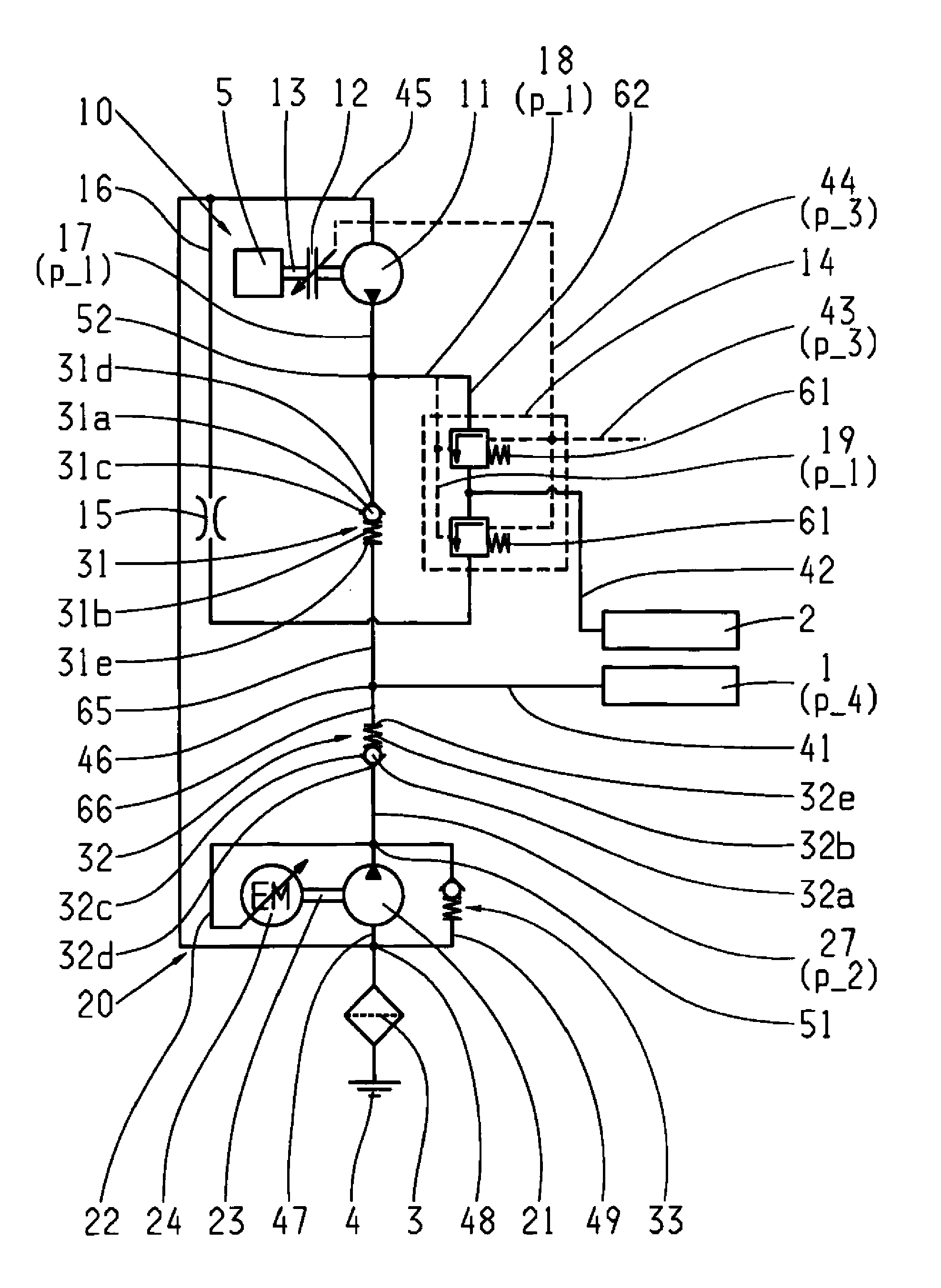
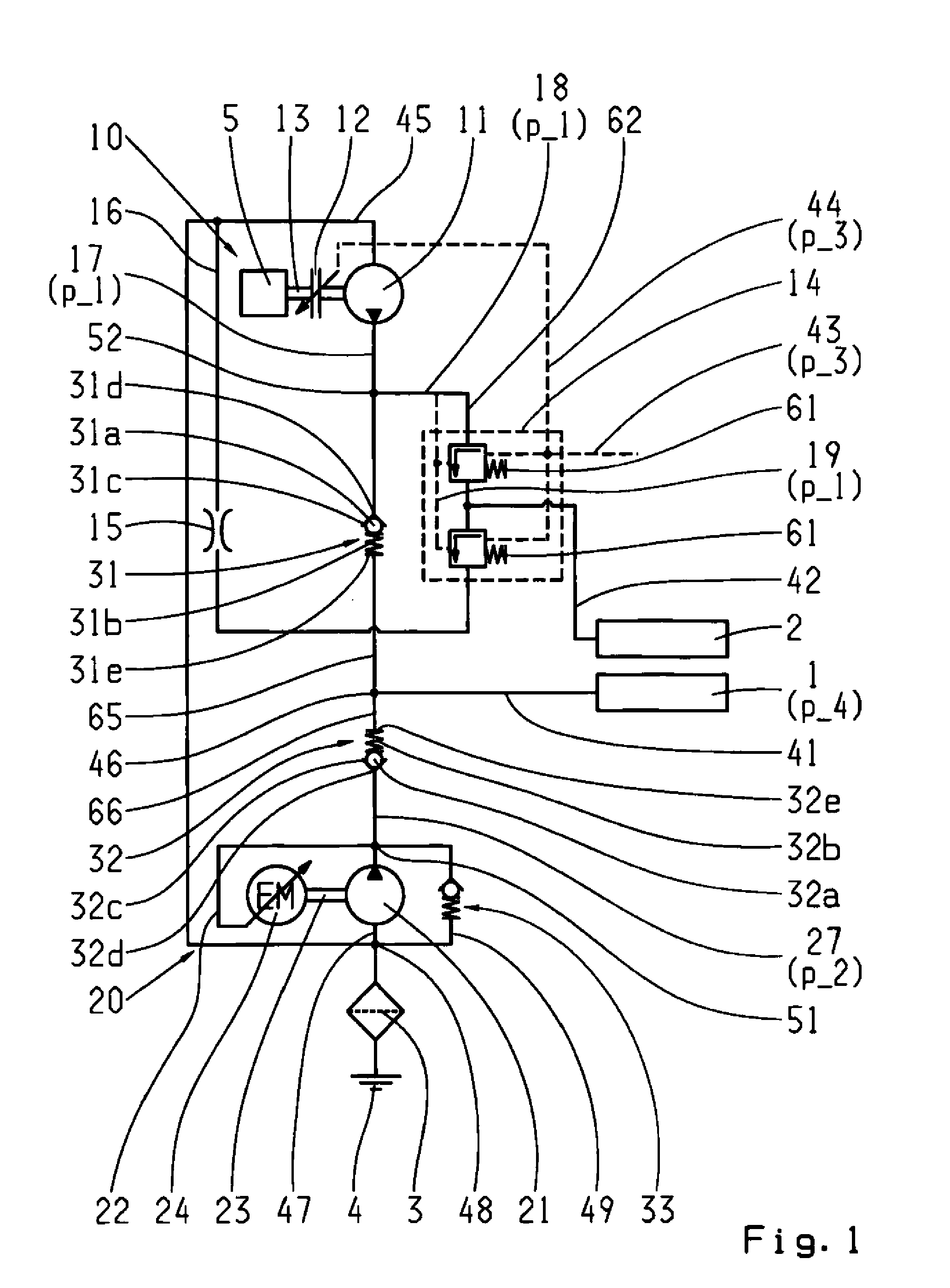
[0037]FIG. 1 shows the hydraulic layout of a vehicle transmission with two mutually independent oil supply units 10 and 20. The oil supply unit 10 comprises a pump 11 made as a displacement pump with fixed displacement volume. The pump 11 can be connected in a rotationally fixed manner by means of a friction clutch12 to a transmission shaft 13, this transmission shaft 13 being driven by an internal combustion engine 5 that serves as the drive unit of the vehicle. In operation, the pump 11 draws in the operating medium, usually oil, through a suction line 45 and a filter 3 from an oil reserve 4. The oil reserve 4 is usually held in an oil sump of a transmission housing. The pump 11 delivers the oil at a pressure p_1 to a pressure line 17 at the other end of which is arranged a one-way valve 31. The one-way valve 31 is made as a seat valve and comprises a closure element 31a, a spring 31b and a valve seat 31c. If the sum of a pressure force of the operating medium at an outlet side 31...


PUM


Abstract

An automatic vehicle transmission comprises a first oil supply unit (10) with at least one mechanically driven first pump (11) and a second oil supply unit (20) with at least one electrically driven second pump (21), and a valve device (14) and a clutch system (1). The second oil supply unit (20) supplies the clutch system (1), during a first operating condition, and the first oil supply unit (10) supplies the clutch system (1), during a second operating condition.

Description

[0001]This application claims priority from German patent application serial no. 10 2009 001 110.2 filed Feb. 24, 2009.FIELD OF THE INVENTION[0002]The invention concerns a transmission hydraulic system for actuating an automatic transmission.BACKGROUND OF THE INVENTION[0003]The oil demand of a hydraulically actuated automatic transmission is the sum of several fractions. A first fraction of the operating medium to be provided by an oil supply system is needed for pressurizing the transmission shift elements required for torque transmission, such as clutches. In a first operating condition in which no shifts to change the gear transmission ratio are carried out, a small volume flow to compensate for leakage losses in the clutches acted upon with a clutch pressure for the corresponding transmission ratios is needed. The operating medium, which can even be other than oil, is therefore under a clutch pressure. For a second operating condition, also referred to as transmission shifting i...

Claims


Application Information

Patent Timeline
Patent Type & Authority Applications(United States)
IPC IPC(8): B60W10/02F16D48/02B60W30/18
CPCF16H61/0031Y10T477/75Y10T477/753
Inventor GRUNDLER, RAINERSCHMIDT, THILOPOPP, CHRISTIANZELLER, HEINRICH
Owner ZF FRIEDRICHSHAFEN AG
Why Eureka
Try Eureka