Laser Processing System and laser Processing Method

a laser processing and laser processing technology, applied in lasers, laser beam welding apparatus, manufacturing tools, etc., can solve the problems of inability to cope with laser processing in which high focusing accuracy is required, and inability to accurately adjust the position of the laser beam and the work. achieve the effect of high accuracy and efficiency, and high accuracy and efficiency

Inactive Publication Date: 2010-09-02
TOYOTA JIDOSHA KK +1
View PDF7 Cites 19 Cited by
  • Summary
  • Abstract
  • Description
  • Claims
  • Application Information

AI Technical Summary

Benefits of technology

[0035]In the laser processing method according to the present invention, a degree of coincidence of the focus position of the processing laser and the surface of the workpiece is specified by the distance between centers of gravity of the spot lights of the two visible lasers. Thus, regardless of a surface shape and a posture (inclination) of the workpiece, it is possible to extremely highly accurately and efficiently perform setting of the focus position. Therefore, in particular, even in remote welding in which setting of a focus position of a processing laser is extremely difficult, highly accurate and efficient setting of a focus position is realized. Thus, it is possible to simultaneously solve both the fall in processing accuracy and the fall in yield that are problems in such remote welding.
[0036]As it is understood from the above explanation, in the laser processing system and the laser processing method according to the present invention, respective center of gravity positions of the spot lights on the surface of the work piece formed by the plural visible lasers are calculated and irradiation of the processing laser is performed in a state in which a distance between centers of gravity is adjusted to zero or substantially zero. Therefore, it is possible to extremely highly accurately and efficiently perform laser processing.

Problems solved by technology

However, with the method of judging possibility of focusing only from a positional relation between one auxiliary laser beam (visible laser) and the main laser beam for processing, it is impossible to cope with laser processing in which high focusing accuracy is required.
Therefore, the distance adjustment between the laser beam and the work is eventually no better than distance adjustment that depends on physical functions of the worker who visually recognizes the screen.
It is still difficult to highly accurately perform position adjustment for the laser beam and the work.

Method used


Image

  • Laser Processing System and laser Processing Method
  • Laser Processing System and laser Processing Method
  • Laser Processing System and laser Processing Method

Examples


Embodiment Construction

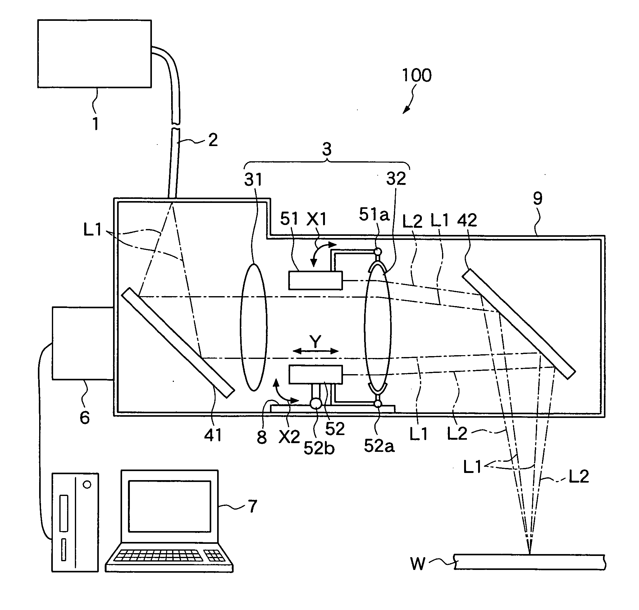
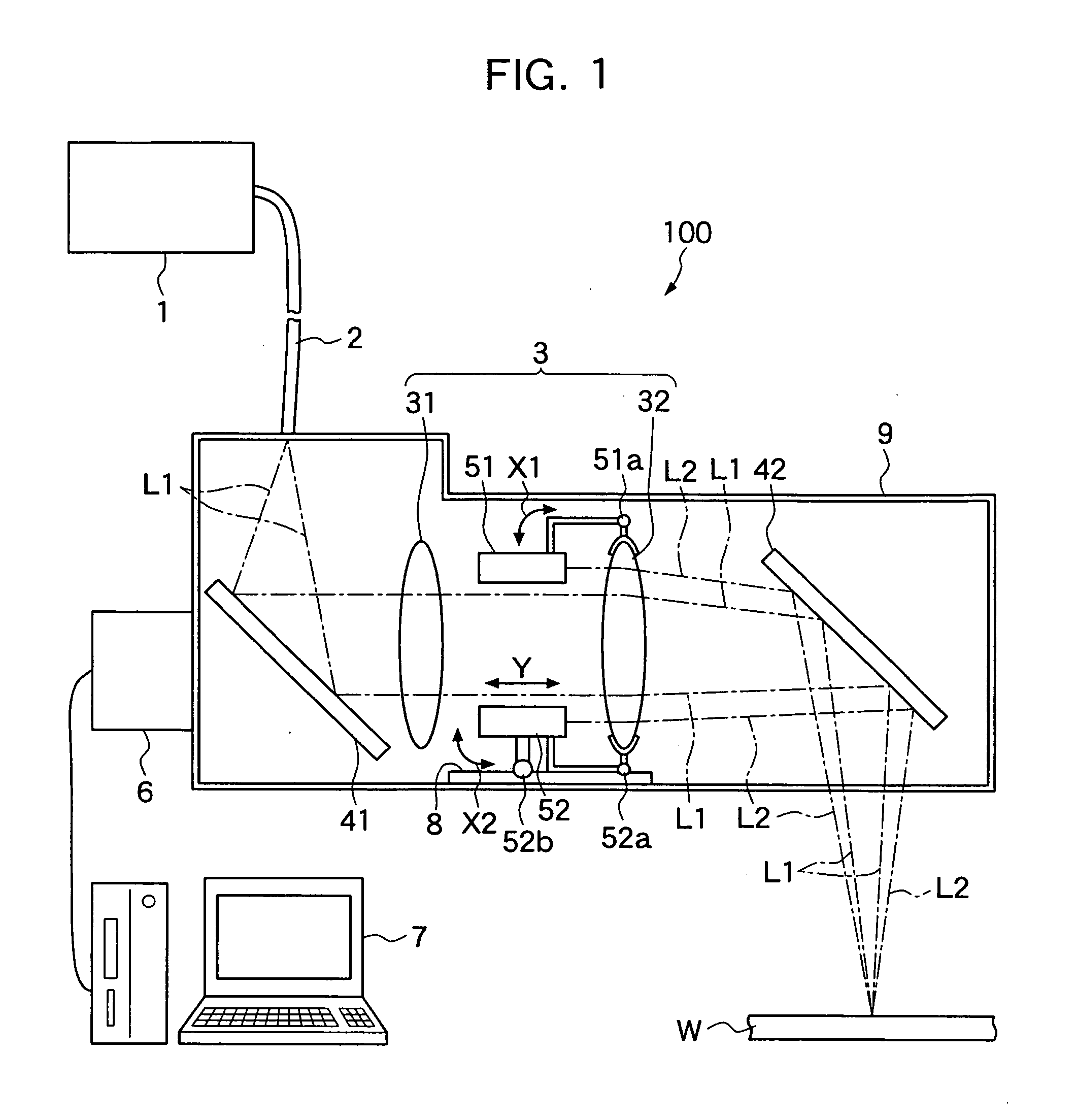
[0049]Embodiments of the present invention will be hereinafter explained with reference to the drawings. FIG. 1 shows a schematic diagram of an embodiment of a laser processing system according to the present invention, FIG. 2 shows a schematic diagram for explaining a state in which a distance between centers of gravity of spot lights of two visible lasers is adjusted by moving a condenser lens, FIG. 3A shows an arrow view taken along III-III in FIG. 2, and FIG. 3B shows a diagram in which the distance between centers of gravity is adjusted to zero. FIG. 4 shows a schematic diagram showing spot light of an elliptical shape, FIG. 5 shows a block diagram of a control mechanism of the laser processing system, FIG. 6 shows a diagram showing an embodiment of a control flow of the laser processing system, and FIG. 7 shows a graph for explaining a relation between a distance between centers of gravity and a condenser lens position. FIG. 8 shows a diagram showing another embodiment of the ...


PUM

PropertyMeasurementUnit
gravityaaaaaaaaaa
distanceaaaaaaaaaa
irradiation angleaaaaaaaaaa

Abstract

A laser processing system and a laser processing method that can highly accurately and efficiently specify a focus position of a processing laser using visible lasers are provided. For that purpose, a laser processing system includes a processing laser oscillator, a condensing optical system including a condenser lens, two visible laser oscillators and, a movement adjusting unit that adjusts the condenser lens and the visible laser oscillators and to move forward and backward in synchronization with each other, an imaging unit that images spot lights of the visible lasers on a workpiece, an image processing unit that subjects an imaged video to image processing and displays an image after the processing, a calculating unit that calculates, in a state in which the respective visible lasers are focused on a focus position of the processing laser, center of gravity positions of spot lights of the respective visible lasers formed on the surface of the workpiece according to the movement of the condenser lens and calculates a distance between centers of gravity, and a control unit that controls the movement adjusting unit such that the distance between centers of gravity is adjusted to zero or substantially zero.

Description

TECHNICAL FIELD[0001]The present invention relates to a laser processing system and a laser processing method, and, more particularly to a laser processing system and a laser processing method that can highly accurately and efficiently specify a focus position of a processing laser using a visible laser.BACKGROUND ART[0002]In laser processing, there is a so-called remote welding method for condensing a laser beam in a distance from a laser oscillator to perform welding while using a condenser lens having a long focus. A processing laser condensed by the condenser lens having a long focus can perform processing of a degree same as that of processing in a focus position even in a position slightly deviating from the focus position. In other words, since it is possible to secure long focal depth in a thickness direction of a workpiece, it is unnecessary to perform strict focus position management.[0003]Incidentally, in order to condense the processing laser in a distance from the laser...

Claims


Application Information

Patent Timeline
Patent Type & Authority Applications(United States)
IPC IPC(8): B23K26/06B23K26/00H01S3/00
CPCB23K26/04
Inventor SATO, AKIOSUZUKI, HIROYUKITSUBOI, AKIHIKO
Owner TOYOTA JIDOSHA KK
Why Eureka
Try Eureka