Magnetic Tunnel Junction Device and Fabrication

Active Publication Date: 2010-09-02
QUALCOMM INC
View PDF16 Cites 67 Cited by
  • Summary
  • Abstract
  • Description
  • Claims
  • Application Information

AI Technical Summary

Benefits of technology

[0006]A capping layer adjacent to a free layer of a MTJ device may be formed of a metal layer and layer of a metal oxide. The capping layer including the metal oxide may reduce a switching current density, while the metal layer may prevent diffusion of

Problems solved by technology

This “spin pumping” effect results in a greater amount of current needed to change a direction of the magnetic moment of the free layer.
However, the additional MgO layer increased the resistance-area product (RA) and degraded the magnetoresistance (MR),

Method used


Image

  • Magnetic Tunnel Junction Device and Fabrication
  • Magnetic Tunnel Junction Device and Fabrication
  • Magnetic Tunnel Junction Device and Fabrication

Examples


Embodiment Construction

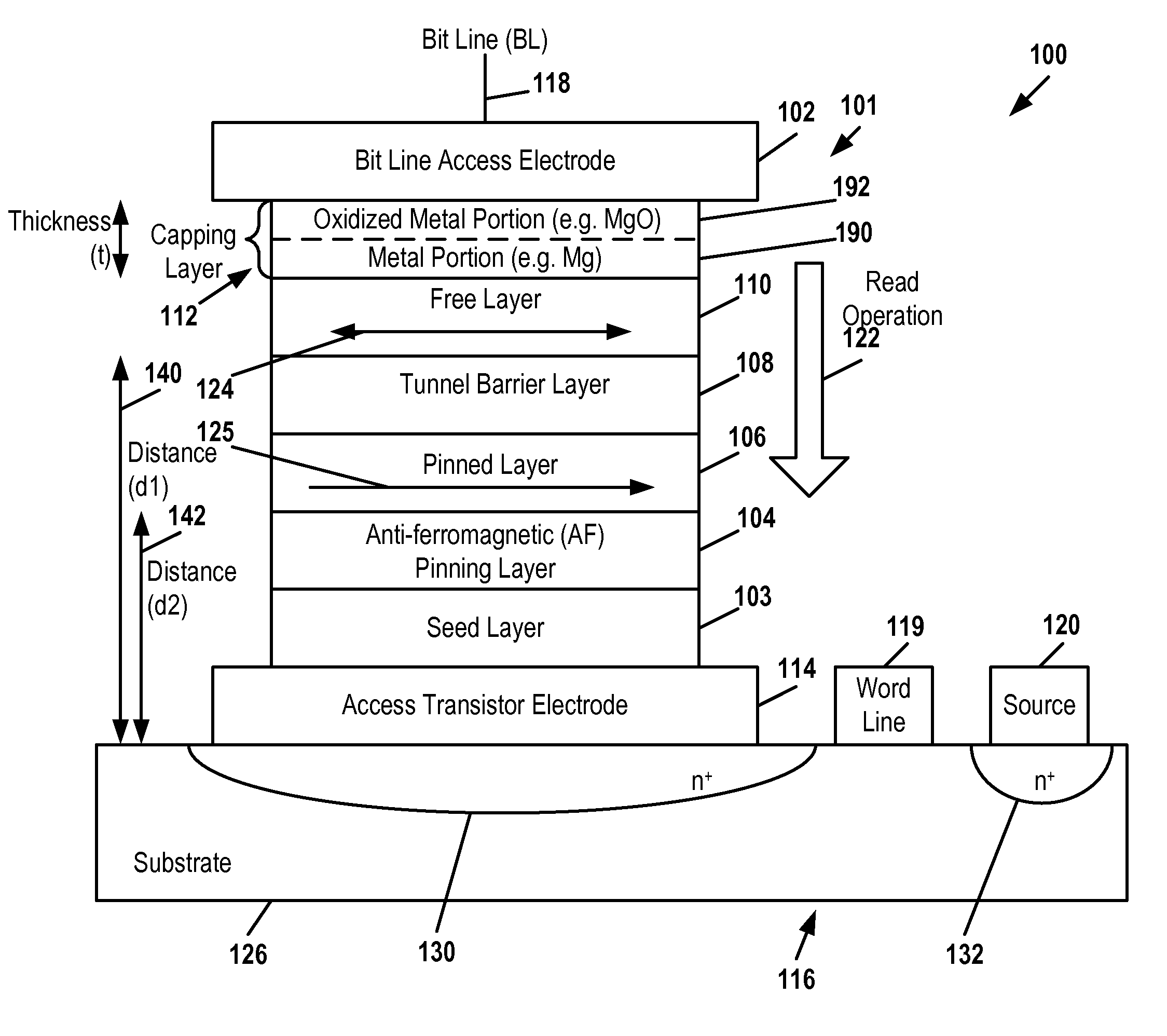
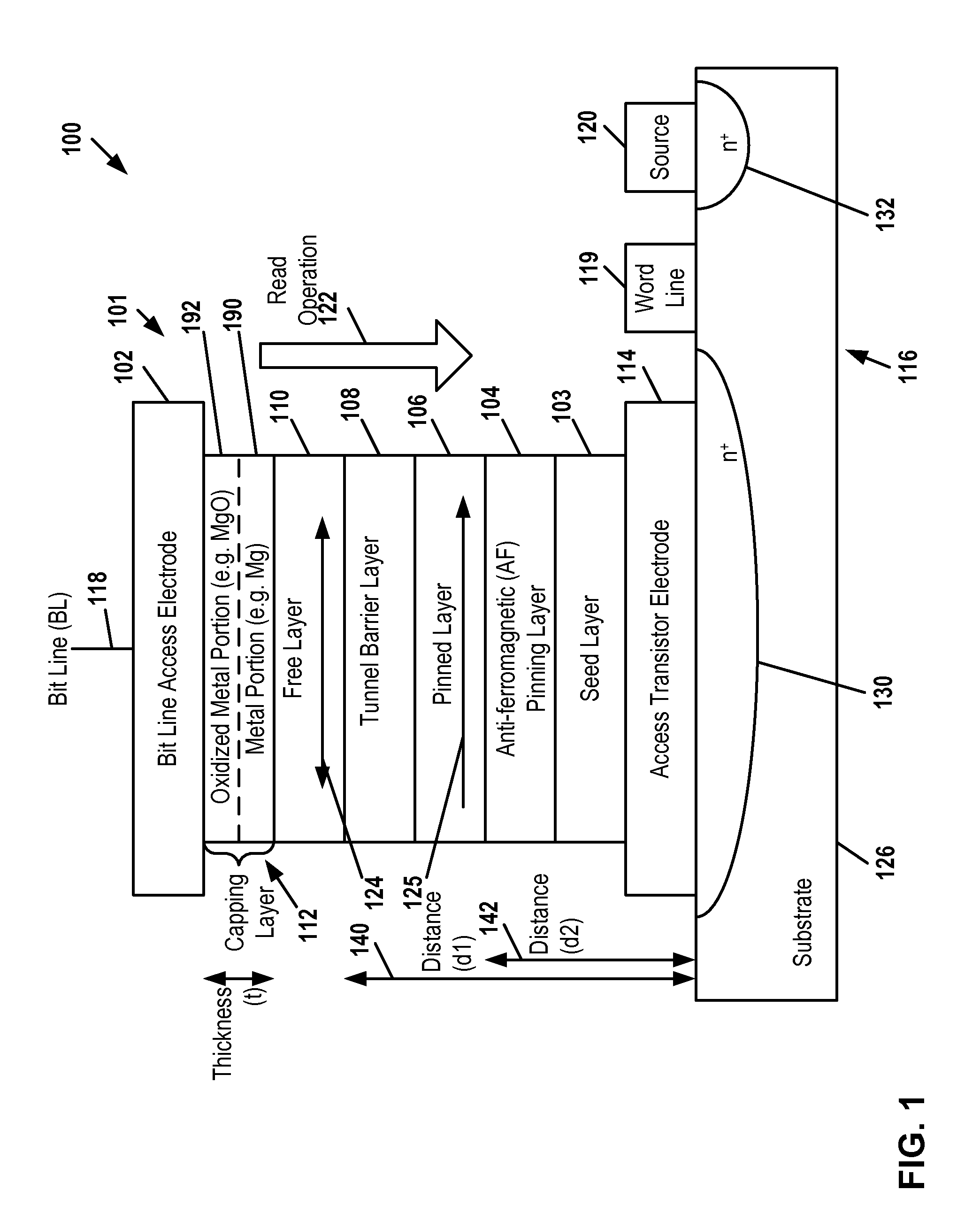
[0018]Referring to FIG. 1, a first illustrative embodiment of an element of a spin-torque-transfer magnetic random access memory (STT-MRAM) is depicted and generally designated 100. The element of the STT-MRAM 100 includes a memory cell having a magnetic tunneling junction (MTJ) device 101 and an access transistor 116 on a substrate 126. The MTJ device 101 includes an access transistor electrode 114, a seed layer 103, an anti-ferromagnetic (AFM) pinning layer 104, a pinned layer 106, a tunnel barrier layer 108, a free layer 110, a capping layer 112, and a bit line access electrode 102 coupled to a bit line 118. The access transistor electrode 114 is coupled to a drain region 130 of the access transistor 116. The access transistor 116 is gated by a word line 119 and has a source region 132 coupled to a source contact 120.

[0019]The seed layer 103 is in contact with the access transistor electrode 114. The seed layer 103 provides a surface for MTJ film deposition and can be composed of...


PUM


Abstract

A magnetic tunneling junction device and fabrication method is disclosed. In a particular embodiment, the method includes depositing a capping material on a free layer of a magnetic tunneling junction structure to form the capping layer and oxidizing a portion of the capping material to form a layer of oxidized material.

Description

I. FIELD[0001]The present disclosure is generally related to magnetic tunneling junction (MTJ) devices and fabrication, and particularly to a MTJ structure that incorporates a capping layer.II. DESCRIPTION OF RELATED ART[0002]MTJ elements may be used to create a magnetic random access memory (MRAM). An MTJ element typically includes a pinned layer, a magnetic tunnel barrier, and a free layer, where a bit value is represented by a magnetic moment in the free layer. A bit value stored by an MTJ element is determined by a direction of the magnetic moment of the free layer relative to a direction of a fixed magnetic moment carried by the pinned layer. The magnetization of the pinned layer is fixed while the magnetization of the free layer may be switched.[0003]When a current flows through the MTJ element, the magnetization direction of the free layer may be changed when the current exceeds a threshold value, i.e. critical switching current (Ic). According to a spin-torque-transfer model...

Claims


Application Information

Patent Timeline
IPC IPC(8): H01L29/82H01L21/283G06F19/00
CPCB82Y25/00B82Y40/00G06F17/5068H01F10/3254H01F41/309H01F10/329H01L27/228H01L43/08H01L43/12H01L43/02H01F41/32G06F30/39H10B61/22H10N50/01H10N50/10H01F10/32H10N50/80
Inventor LEE, KANGHOZHU, XIAOCHUNLI, XIAKANG, SEUNG H.
Owner QUALCOMM INC
Why Eureka
Try Eureka