
Solar thermal receiver and solar thermal power generation facility

a technology solar thermal receiver, which is applied in the direction of machines/engines, transportation and packaging, light and heating equipment, etc., can solve the problems of high cost, difficult and low efficiency, so as to improve the power generation efficiency of solar thermal power generation, enhance the thermal shock resistance, and reduce the production cost

Inactive Publication Date: 2010-09-09
MITSUBISHI HEAVY IND LTD
View PDF12 Cites 19 Cited by
  • Summary
  • Abstract
  • Description
  • Claims
  • Application Information

AI Technical Summary

Benefits of technology

[0039]According to the solar thermal receiver of the first aspect of the present invention and the solar thermal power generation facility of the second aspect thereof, because a coating layer having a thermal barrier property is provided, an advantage is afforded in that it is possible to improve power generation efficiency in solar thermal power generation, to reduce the production cost, and to enhance the thermal shock resistance.

Problems solved by technology

However, merely with a method of improving the solar heat absorption efficiency, there is an upper limit to the absorption efficiency, and thus there is also an upper limit to the improvement in fluid heating efficiency, leading to a problem of difficulty in further improving the power generation efficiency.
When a solar thermal receiver is made of porous ceramic etc., there is a problem in that it is easily damaged because the porous ceramic has low thermal shock resistance, and the cost is high.
Further, there is a problem in that the production cost is high when the solar thermal receiver is made of porous ceramic etc.

Method used


Image

  • Solar thermal receiver and solar thermal power generation facility
  • Solar thermal receiver and solar thermal power generation facility
  • Solar thermal receiver and solar thermal power generation facility

Examples


first embodiment

[0048]A solar thermal power generation facility according to a first embodiment of the present invention will be described below with reference to FIGS. 1 to 4.

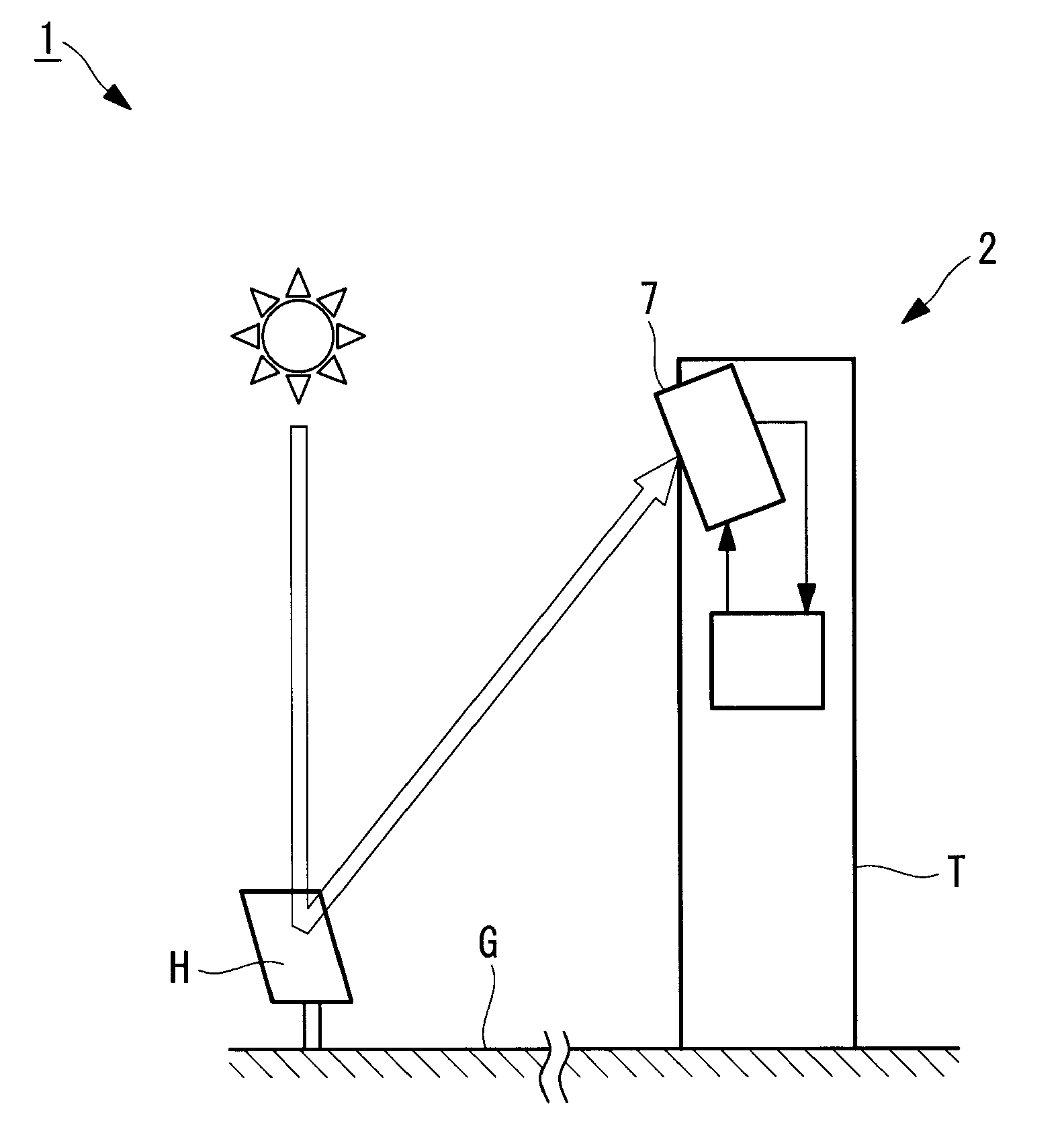
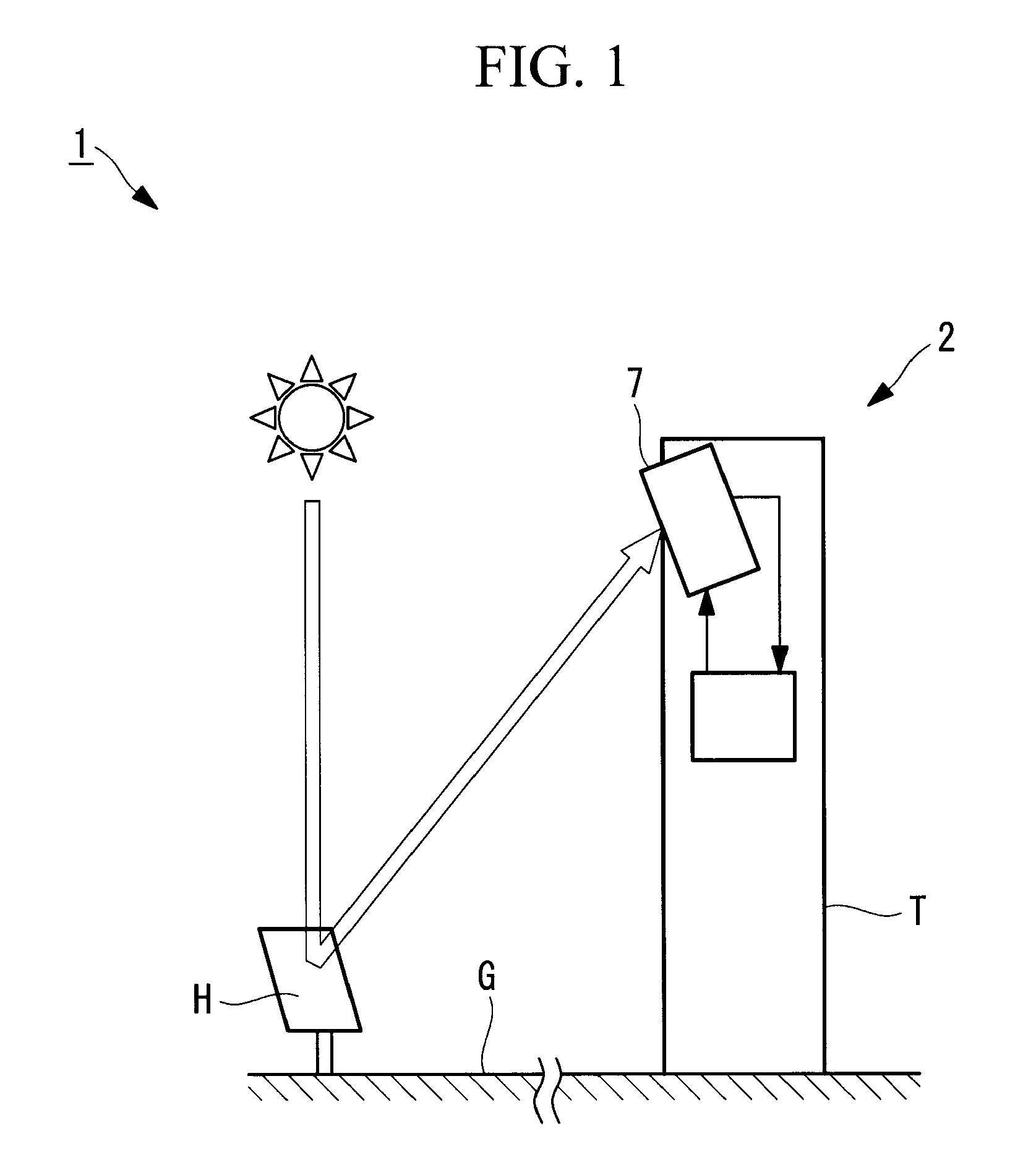
[0049]FIG. 1 is a schematic diagram for explaining, in outline, the solar thermal power generation facility according to this embodiment.

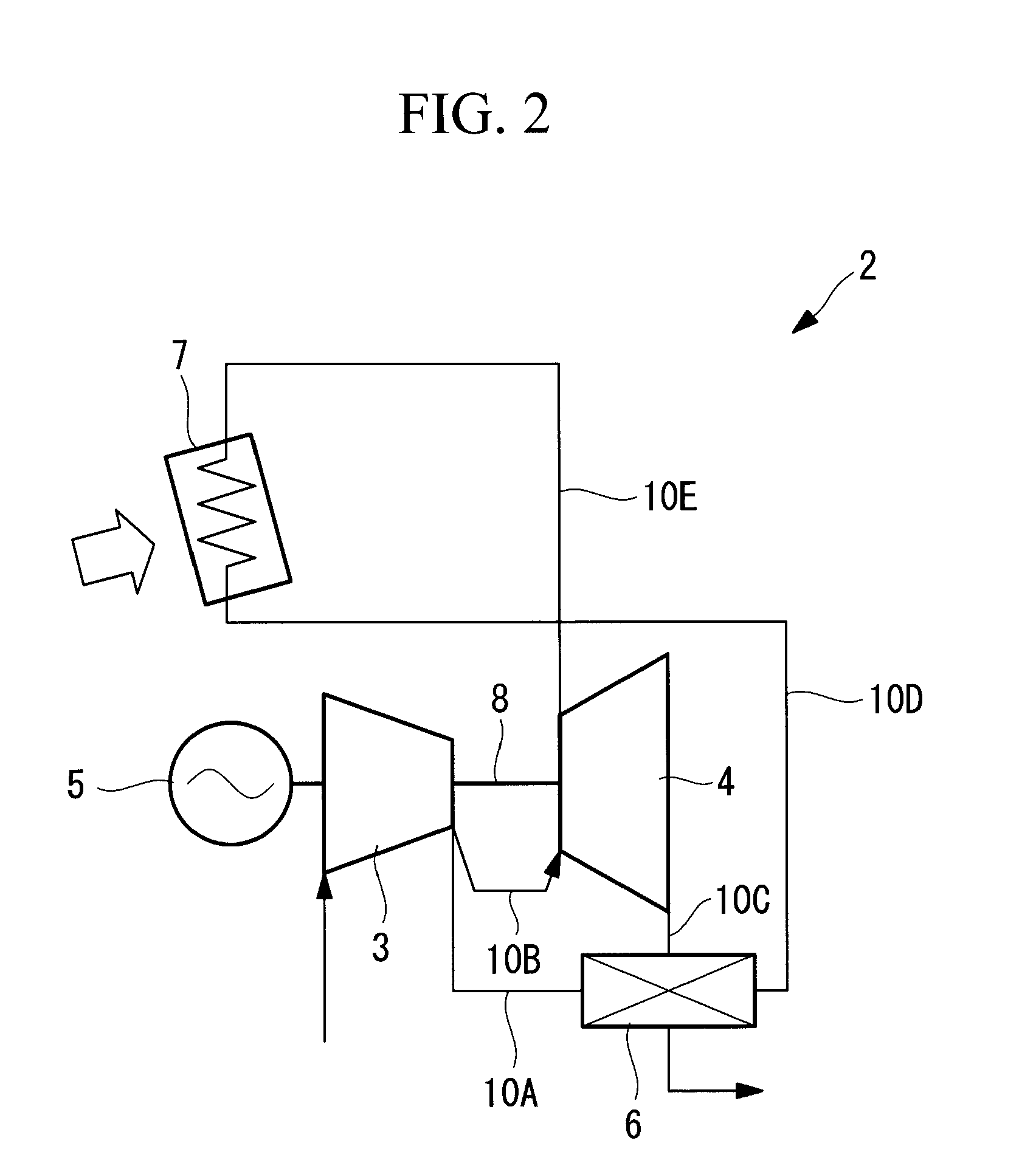
[0050]As shown in FIG. 1, a solar thermal power generation facility 1 converts energy of sunlight into heat (solar heat) and generates power by utilizing the heat. In this embodiment, a description will be given of the solar thermal power generation facility 1 that is a so-called solar thermal gas turbine obtained when a configuration in which a power generator 5 is driven by using a gas turbine is combined with a configuration in which power is generated by utilizing solar heat.

[0051]Note that the solar thermal power generation facility 1 may be of the solar thermal gas turbine type, as described above, or may be another type using a steam turbine or the like; the type thereof is not partic...

second embodiment

[0119]Next, a second embodiment of the present invention will be described with reference to FIGS. 5 and 6.

[0120]In a solar thermal power generation facility of this embodiment, the basic configuration is the same as that of the first embodiment but the configuration of a thermal receiver is different from that of the first embodiment. Therefore, in this embodiment, a description will be given of only the thermal receiver and its surroundings by using FIGS. 5 and 6, and a description of the other components etc. will be omitted.

[0121]FIG. 5 is a schematic diagram for explaining the configuration of the thermal receiver in the solar thermal power generation facility according to this embodiment.

[0122]Note that identical reference numerals are assigned to the same components as those of the first embodiment, and a description thereof will be omitted.

[0123]As in the first embodiment, a thermal receiver 107 of a solar thermal power generation facility 101 of this embodiment is disposed ...


PUM

PropertyMeasurementUnit
temperatureaaaaaaaaaa
heat-resistant temperatureaaaaaaaaaa

Abstract

A solar thermal receiver capable of improving the power generation efficiency in solar thermal power generation, reducing the production cost, and enhancing the thermal shock resistance and a solar thermal power generation facility using the solar thermal receiver are provided. The solar thermal receiver that receives solar radiation to heat fluid includes a heat-receiving section that is made of metal and that constitutes a flow path in which at least the fluid flows; and a coating layer that is disposed on at least a surface of an area of the heat-receiving section irradiated with the sunlight, that absorbs energy of the sunlight, and that has heat resistance.

Description

BACKGROUND OF THE INVENTION[0001]1. Field of the Invention[0002]The present invention relates to solar thermal receivers and solar thermal power generation facilities.[0003]This application is based on Japanese Patent Application No. 2009-053466, the content of which is incorporated herein by reference.[0004]2. Description of Related Art[0005]Various types of power generation facilities utilizing solar heat have been conventionally proposed. For example, power generation facilities have been proposed in which fluid compressed by a compressor is heated by absorbing solar heat, the heated fluid is supplied to a turbine section to extract a rotary drive force, and a power generator is rotationally driven (for example, see PCT International Publication No. WO 2006-025449 Pamphlet and U.S. Pat. No. 4,268,319).[0006]Since solar thermal receivers that make fluid absorb solar heat are required to make the fluid absorb heat from sunlight efficiently, various configurations have been proposed...

Claims


Application Information

Patent Timeline
Patent Type & Authority Applications(United States)
IPC IPC(8): F03G6/00F24J2/48F24S10/70F24S23/70
CPCF24J2/07F24J2/26F24J2/485Y02E10/44Y02E10/41Y02E10/46F24J2002/261F28F19/02F24S70/20F24S10/75F24S20/20F24S2010/751F24S2080/011Y02E10/40
Inventor MASADA, JUNICHIROHADA, SATOSHIIIJIMA, TAKAYOSHI
Owner MITSUBISHI HEAVY IND LTD
Learn More