
Fuses of semiconductor device and method of forming the same

a technology of semiconductor devices and fuse residues, which is applied in the direction of semiconductor devices, semiconductor/solid-state device details, electrical equipment, etc., can solve the problems of reducing yield, wasting and reducing the energy and spot size of lasers applied when blowing fuse residues. , to achieve the effect of preventing the formation of fuse residues, reducing the energy and spot size of lasers, and preventing damage to neighbor

Inactive Publication Date: 2010-09-09
SK HYNIX INC
View PDF4 Cites 10 Cited by
  • Summary
  • Abstract
  • Description
  • Claims
  • Application Information

AI Technical Summary

Benefits of technology

[0009]The fuse preferably further comprises a barrier metal layer formed between the first dielectric interlayer and the fuse metal and configured to control tensile force and the occurrence of a crack. Here, the barrier metal layer controls a state in which the crack is easily caused in the fuse metal through control of tensile force or high energy applied to cause the crack such that the crack is easily generated in the fuse metal with a laser of a small energy.
[0011]The first dielectric interlayer preferably is made of oxide, nitride, carbon series, polymer-series materials, or a combination thereof. The above materials can easily control tensile force such that the crack is caused in the fuse metal.
[0012]The polymer-series materials preferably comprise polyimide, polypropylene, and polyvinyl chloride (PVC), or a combination thereof. Here, general polymer-series materials may be used. In particular, polyimide causes very strong tensile force in the fuse metal when the fuse metal is made of copper (Cu). Thus, a crack can be easily caused in the fuse metal even by small laser energy.
[0014]The fuse preferably further comprises a barrier metal layer formed between the fuse metal and the second dielectric interlayer and configured to control tensile force and the occurrence of a crack. Here, the barrier metal layer controls a state in which the crack is easily caused in the fuse metal through control of tensile force or high energy applied to cause the crack such that the crack is easily generated in the fuse metal with a laser of a small energy.
[0016]The second dielectric interlayer preferably is made of oxide, nitride, carbon series, polymer-series materials, or a combination thereof. The above materials can easily control tensile force such that the crack is caused in the fuse metal.
[0026]Advantages of the preferred embodiment may include one or more of the following. Formation of fuse residues when blowing a fuse can be prevented. Furthermore, energy and a spot size of a laser applied when blowing a fuse can be reduced. Moreover, damage to neighboring fuses can be prevented, and a fuse made of materials that are difficult to blow the fuse can be cut. Further, since polymer-series materials are used as a dielectric interlayer, the coupling effect between wiring lines can be reduced significantly.

Problems solved by technology

If any one of the memory cells is faulty, a corresponding semiconductor device is determined to be faulty, resulting in a lowered yield.
However, to discard the entire semiconductor device as being a faulty product although only some of the cells have failed is wasteful.
If residue is generated during blowing a fuse, a fail can occur because there may still be an electrical connection caused by the residue particles.
Accordingly, a problem arises because the yield of semiconductor devices is reduced.

Method used


Image

  • Fuses of semiconductor device and method of forming the same
  • Fuses of semiconductor device and method of forming the same
  • Fuses of semiconductor device and method of forming the same

Examples


Embodiment Construction

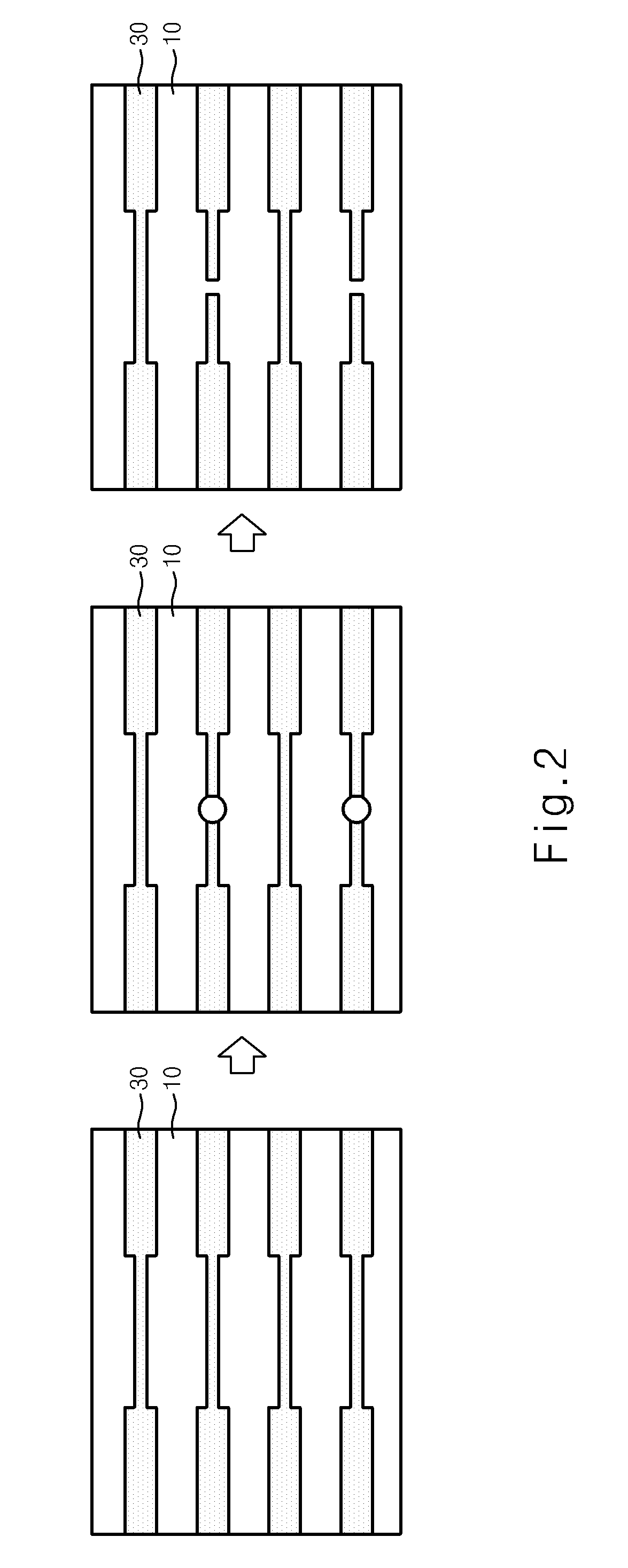
[0029]FIGS. 1 and 2 are a cross-sectional view and a plan view of a fuse according to an embodiment of the present invention.

[0030]It is to be noted that, although only one fuse element is illustrated in FIG. 1 and described, a number of the fuse elements are arranged as shown in FIG. 2. In more detail, a memory cell array (not shown), a redundant memory cell array (not shown) for replacing a faulty memory cell of the memory cell array, and a number of fuse elements for blocking a path to the faulty memory cell and inputting and outputting data to and from a corresponding redundant memory cell are arranged.

[0031]As shown in FIG. 1, the fuses of a semiconductor device according to the embodiment of the present invention each include a dielectric interlayer 10, a barrier metal layer 20, and a fuse metal 30. Although not shown in FIG. 1, another dielectric interlayer (not shown) may be further formed on the fuse metal 30. Hereinafter, an exposed fuse as shown in FIG. 1 is described as ...


PUM

PropertyMeasurementUnit
temperatureaaaaaaaaaa

Abstract

Devices and methods are disclosed a dielectric interlayer made of materials capable of forming tensile force is formed over a semiconductor substrate, and a fuse metal having stronger tensile force than the first dielectric interlayer is formed over the first dielectric interlayer. Accordingly, formation of fuse residues when blowing a fuse can be prevented. Furthermore, energy and a spot size of a laser applied when blowing a fuse can be reduced. Moreover, damage to neighboring fuses can be prevented, and a fuse made of materials that are difficult to blow the fuse can be cut. Further, since polymer-series materials are used as a dielectric interlayer, the coupling effect between wiring lines can be reduced considerably.

Description

CROSS-REFERENCE TO RELATED APPLICATION[0001]The priority of Korean patent application No. 10-2009-0019891 filed Mar. 9, 2009, the disclosure of which is hereby incorporated in its entirety by reference, is claimed.BACKGROUND OF THE INVENTION[0002]The present invention relates to a semiconductor device and a method of forming the same, and more particularly, to semiconductor fuses, which are capable of fundamentally preventing fuse residue from occurring when blowing a fuse.[0003]Semiconductor devices, such as a memory device and memory merged logic (MML), each include numerous memory cells for storing data. If any one of the memory cells is faulty, a corresponding semiconductor device is determined to be faulty, resulting in a lowered yield. However, to discard the entire semiconductor device as being a faulty product although only some of the cells have failed is wasteful. Accordingly, a memory device or a semiconductor device including a large amount of memory requires a repair fu...

Claims


Application Information

Patent Timeline
Patent Type & Authority Applications(United States)
IPC IPC(8): H01L23/525H01L21/768
CPCH01L23/5258H01L23/5329H01L2924/0002H01L2924/00H01L23/62
Inventor JANG, CHI HWAN
Owner SK HYNIX INC
Learn More