Braking System For Motor Vehicles

a technology for braking systems and motor vehicles, applied in the direction of fluid actuated brakes, rotary clutches, fluid couplings, etc., can solve the problems of energy inefficiency, reaction effect on the brake pedal, so as to promote the failure of the braking system

Inactive Publication Date: 2010-09-09
CONTINENTAL TEVES AG & CO OHG
View PDF13 Cites 30 Cited by
  • Summary
  • Abstract
  • Description
  • Claims
  • Application Information

AI Technical Summary

Benefits of technology

[0017]An object of the present invention is therefore to propose a braking system of the generic type mentioned at the beginning in which it is possible to dispense with complex, energetically unfavorable buffering of hydraulic actuating energy, which promotes failure of the braking system.
[0021]Another advantageous development of the invention consists in the fact that the simulation device is assigned to a first brake booster pressure medium circuit, and the pressure generating device is assigned to a second brake booster pressure medium circuit, wherein, while the braking system is operating, no exchange of pressure medium takes place between the first and second brake booster pressure medium circuits and the wheel brake circuits. As a result of these measures, the operational reliability of the braking system according to aspects of the invention is considerably increased since a possible leakage in one of the hydraulic circuits does not affect the other hydraulic circuits.
[0022]In another refinement of the subject matter of the invention, the pressure generating device is connected to a chamber of the second pressure medium reservoir vessel which is at atmospheric pressure, with the intermediate connection of an electrically switchable 2 / 2 way valve. Of course, it is also possible for the keeping available of the pressure medium supply at the atmospheric pressure level to be effected, as is customary in brake technology, by means of a snifting bore, a tilting valve or a central valve. The electrically switchable 2 / 2 way valve provides, however, the advantage that the actuator of the pressure generating device can, if necessary, start to increase the pressure immediately, and not only after a valve switching travel has been executed.

Problems solved by technology

In conventional braking systems, this leads to a reaction on the brake pedal.
This reaction effect on the brake pedal can be surprising and unpleasant for the driver, with the result that in a critical situation of road traffic the driver does not actuate the brake pedal to a degree which is adapted to this situation since he is irritated by the reaction on the brake pedal which he cannot predict.
It is considered disadvantageous with the previously known braking system that the actuating energy which is necessary to operate it has to be kept available in a high pressure accumulator whose pressure medium flows into the wheel brake circuits during actuation of the brakes.
On the one hand, it is energetically inefficient firstly to raise the pressure medium to the high pressure level of the high pressure accumulator even though only a fraction of this accumulator pressure level is required for the majority of braking operations, and on the other hand this entails the risk that in the event of possible contamination of the pressure medium by gas bubbles, the braking system can fail as a result of the fact that the volume expansion of the gas bubbles which is associated with the flow out of the high pressure accumulator said gas bubbles can expel from the braking lines a column of liquid which is necessary for the hydraulic transmission of force.

Method used


Image

  • Braking System For Motor Vehicles
  • Braking System For Motor Vehicles
  • Braking System For Motor Vehicles

Examples


Embodiment Construction

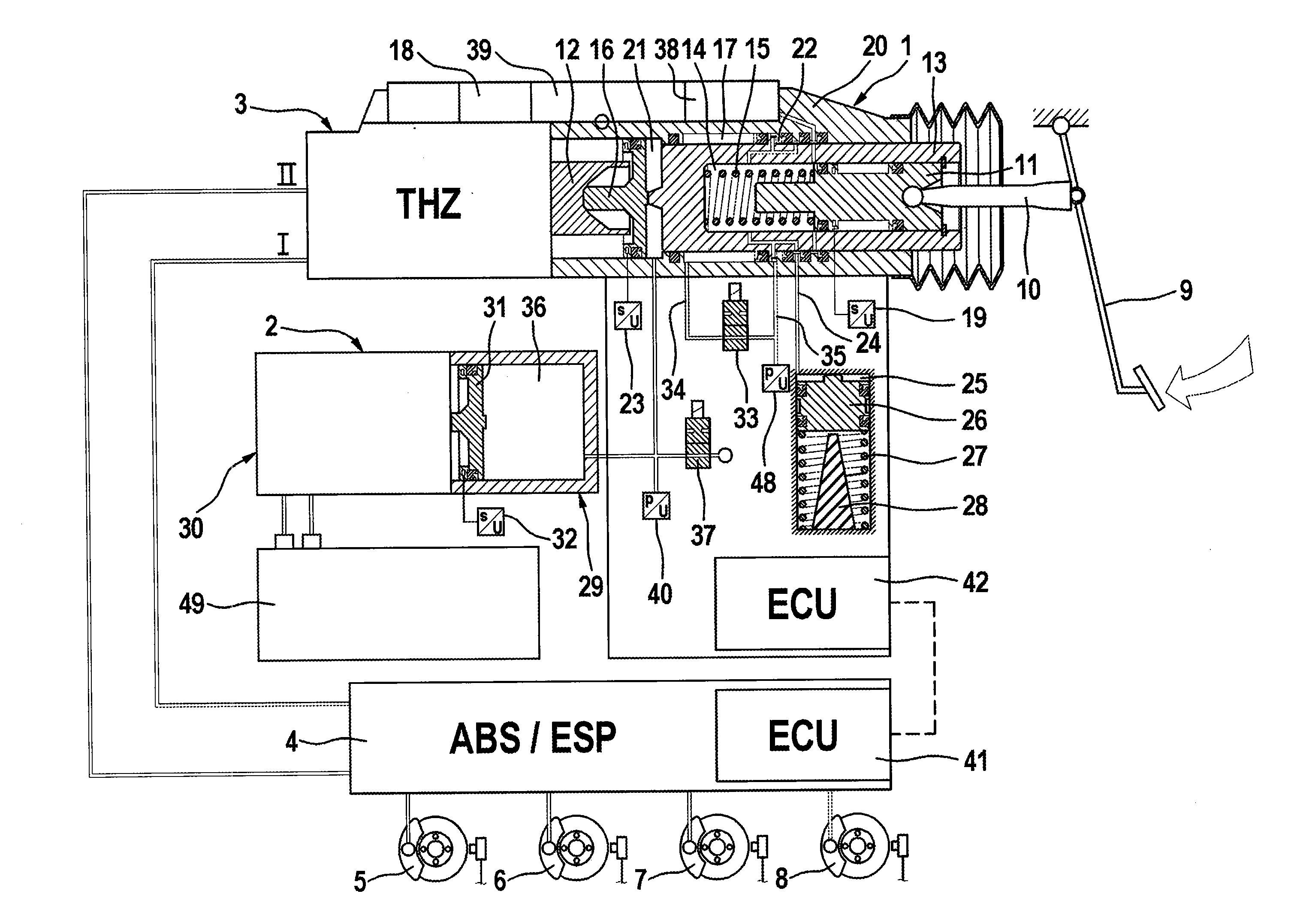
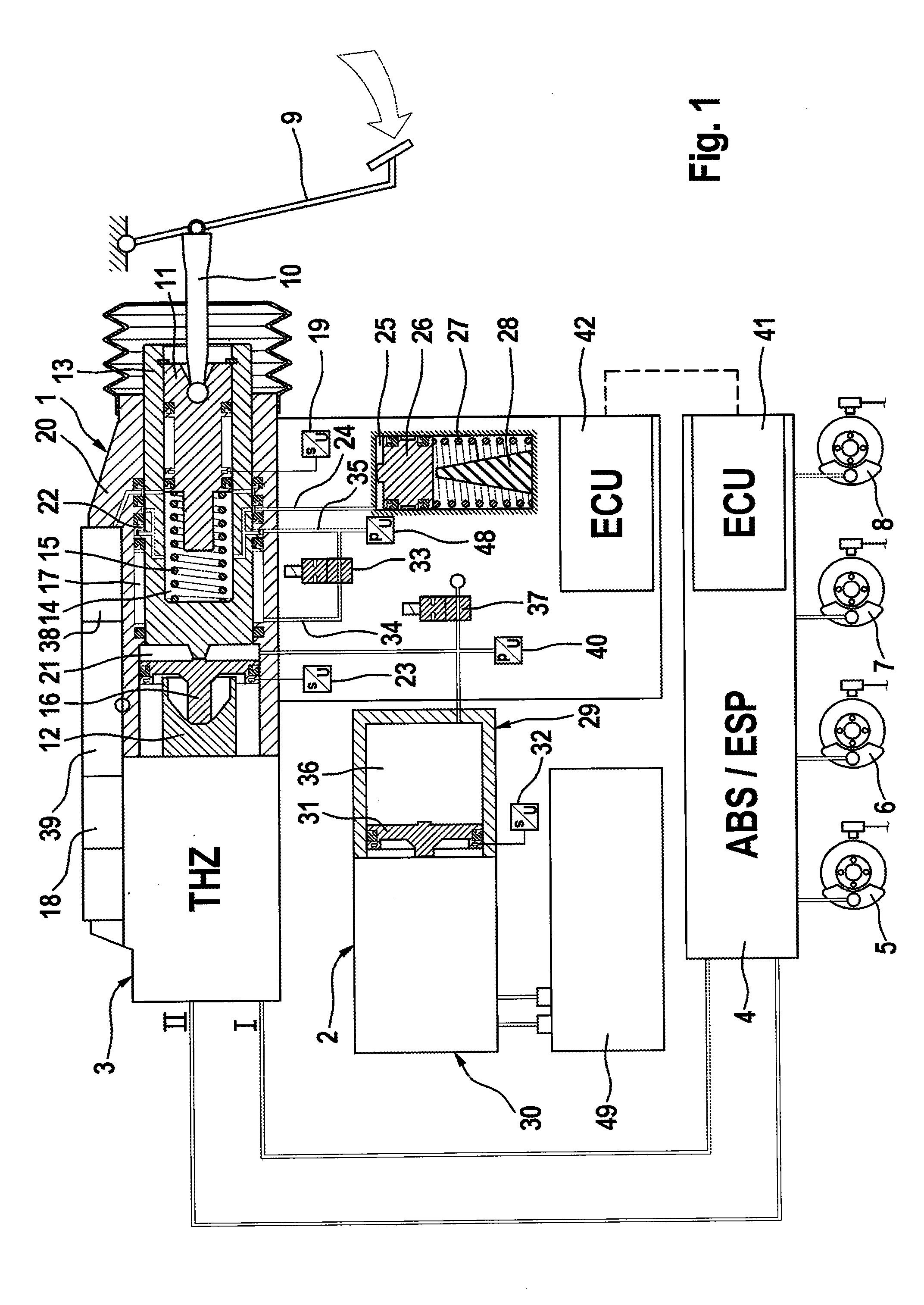
[0027]The braking system according to aspects of the invention which is illustrated in the drawing is composed essentially of an actuating device 1, a pressure generating device 2—with the actuating unit and the pressure generating device forming a brake booster—and a master brake cylinder or tandem master cylinder 3 which is effectively connected downstream of the brake booster and whose pressure spaces (not illustrated) can be connected to the chambers of a first pressure medium reservoir 18 which are at atmospheric pressure. On the other hand, wheel brake circuits I, II, which, with intermediate connection of a known ABS or ESP hydraulic assembly or of a controllable wheel brake pressure modulation module, supply the wheel brakes 5-8 of a motor vehicle with hydraulic pressure medium, are connected to the pressure spaces. An electronic open-loop and closed-loop control unit 41 is assigned to the wheel brake pressure modulation module 4. The actuating device 1, which is arranged in...


PUM


Abstract

A braking system having a master cylinder to which wheel brake circuits (I, II) can be connected, a first piston coupled to a brake pedal, a second piston by means of which the master cylinder is actuated, a third piston actuated by the first piston and connected in a force transmitting fashion to the second piston, a simulation device which gives the driver of the vehicle a pedal sensation, an intermediate space between the second piston and third piston, a hydraulic chamber which is bounded by the third piston and when necessary, a movement of the third piston in the actuating direction is prevented, a pressure generating device which controls the pressure in the intermediate space, a pressure medium reservoir vessel which is under atmospheric pressure and which can be connected hydraulically to the intermediate space, and means for electrically controlling the pressure in the intermediate space.

Description

CROSS REFERENCE TO RELATED APPLICATIONS[0001]This application is the U.S. National Phase Application of PCT International Application No. PCT / EP2007 / 058989, filed Aug. 29, 2007, which claims priority to German Patent Application No. DE 10 2006 040 424.6, filed Aug. 29, 2006, the contents of such applications being incorporated by reference herein.BACKGROUND OF THE INVENTION[0002]1. Field of the Invention[0003]The invention relates to a braking system for motor vehicles having[0004]a master cylinder to which wheel brake circuits are connected,[0005]a first piston which is coupled to a brake pedal via a pressure rod which transmits actuating forces,[0006]a second piston by means of which the master cylinder is actuated,[0007]a third piston which can be actuated by the first piston and which can be connected in a force transmitting fashion to the second piston,[0008]having a simulation device with at least one elastic element which gives the driver a pleasant pedal sensation,[0009]havi...

Claims


Application Information

Patent Timeline
Patent Type & Authority Applications(United States)
IPC IPC(8): B60T13/128
CPCB60T8/4077
Inventor DRUMM, STEFAN
Owner CONTINENTAL TEVES AG & CO OHG
Why Eureka
Try Eureka