Mass produced composite wind turbine blades

Active Publication Date: 2010-09-09
SUSTAINABLE STRUCTURES
View PDF21 Cites 26 Cited by
  • Summary
  • Abstract
  • Description
  • Claims
  • Application Information

AI Technical Summary

Benefits of technology

[0023]Accordingly, one object of the invention is to produce low cost, efficiently produced blades for use in vertical and horizontal axis turbines. A second object of the invention is to replace complex systems of mechanical pivots, stops/springs and cams with simpler, more robust systems to allow pitch control and pivoting of turbine blades through the rotational cycle of a turbine. Practical systems suited to addressing emerging needs for locally produced renewable energy in populated areas with Class 2 and Class 3 (moderate) winds are another object of the invention.
[0024]To address these objectives, a first aspect of the invention is to provide a single cavity, pultruded airfoil shape that ca

Problems solved by technology

But they require a massive thickness of expensive composite materials at the blade root and roughly 600 man-hours of labor for each blade.
They are not economical in areas with moderate winds because of the cost elements cited above, the cost of the heavy nacelle assembly and its structural support, costs of the grid interface and the mechanism for directing the turbine into the wind.
As manufacturers have steadily increased the size of the turbines and built more of them, cost per kilowatt hour has gone up .
One drawback of this approach was illustrated within the report on the August 2003 power outage: Electricity purchased from utilities outside of service areas grew from 18% of total use in 1989 to about 40% of total use in 2002.
Moving enough electricity across the country to both meet existing needs and electric vehicle needs from wind sites in the Great Plains area will require very expensive high voltage transmission lines and corridors.
Writing off functioning coal fired power plants before they are obsolete is beyond the economic capabilities of the country.
The mechanical complexity of the pitch control, however, may have been a factor contributing to the displacement of vertical turbines by horizontal turbines over the past two decades.
. . not a significant improvem

Method used


Image

  • Mass produced composite wind turbine blades
  • Mass produced composite wind turbine blades
  • Mass produced composite wind turbine blades

Examples


Embodiment Construction

Support Stanchion with Integrated Vehicle Charging System

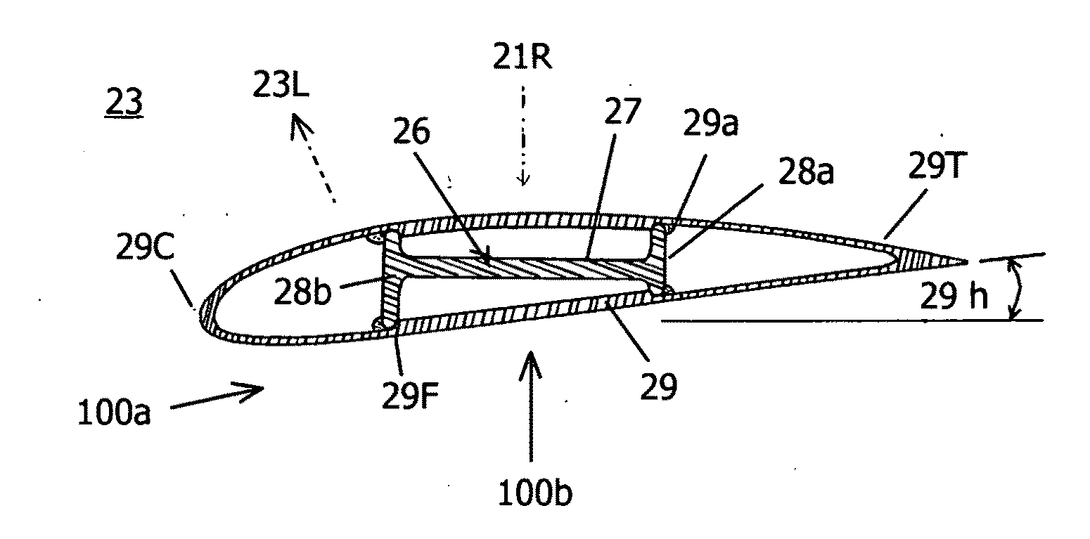
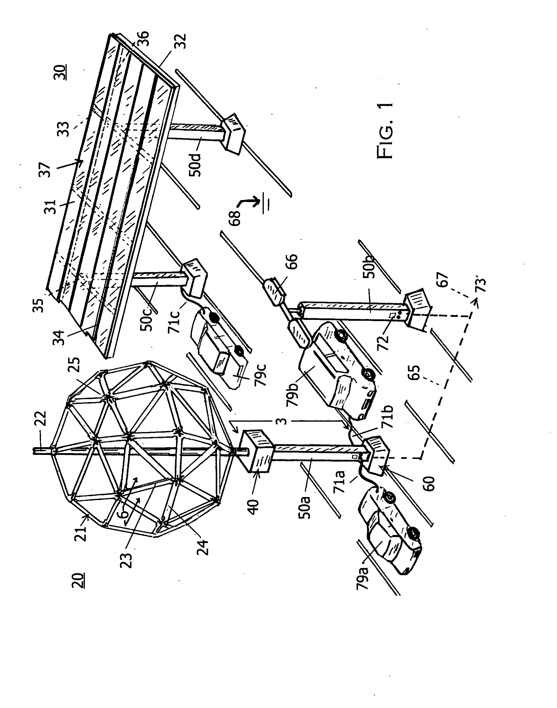
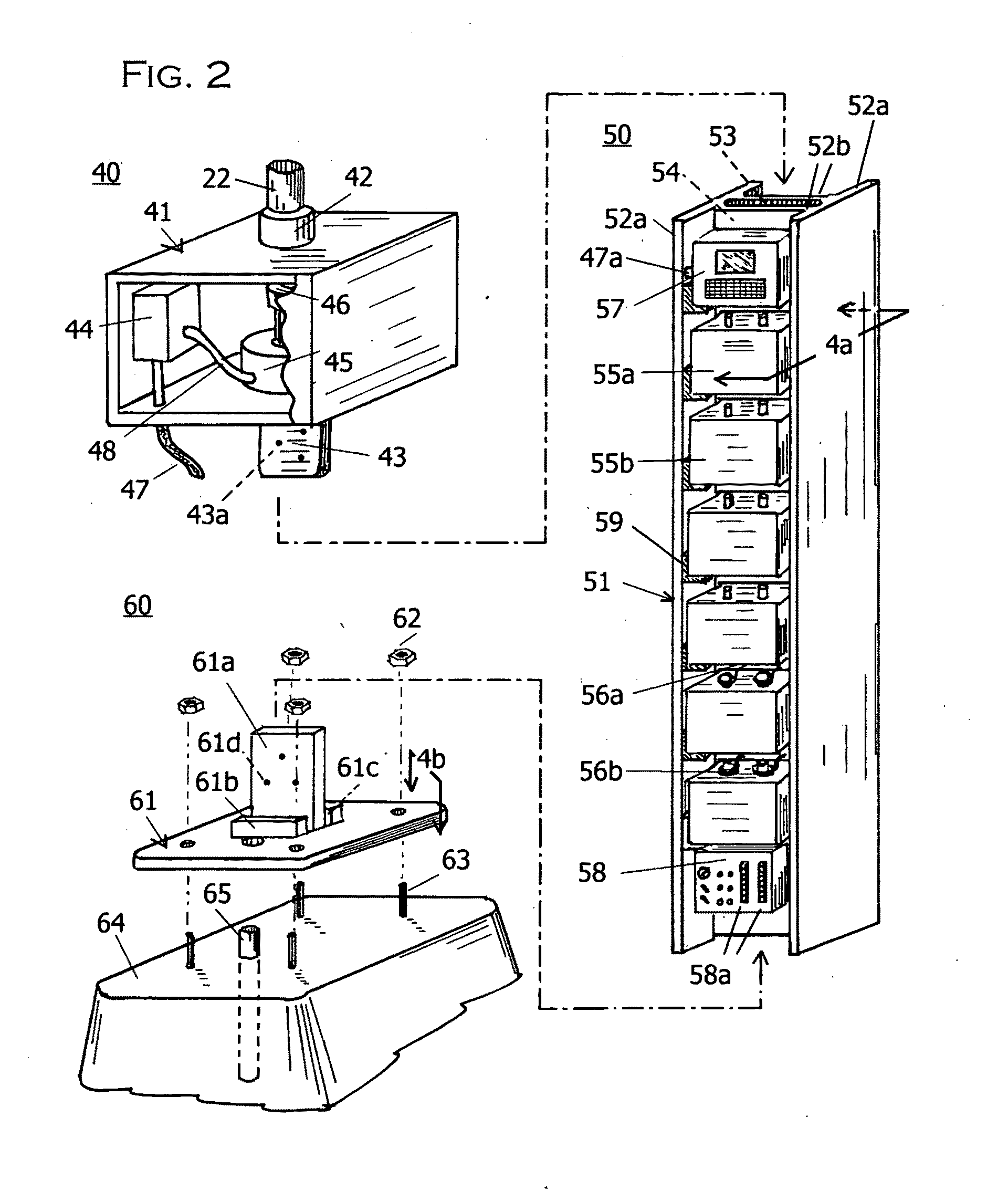
[0045]1. FIGS. 1 through 5 disclose the invention of application Ser. No. 12 / 381,104: A composite stanchion 50 and associated electric equipment with the capability to both support a vertical axis wind turbine rotor 21 and to store / supply energy for hybrid or electric vehicles 79. Stanchion 50 can also support an elevated solar array 30 having an adjustable pitch mechanism for optimum solar collection capability.

[0046]2. Through public facilities to provide for direct supply of vehicle energy from renewable sources; new demand on an already stressed grid structure and carbon emissions from vehicle sources can both be minimized. Additionally, the renewable energy supplied from the invention can be easily utilized for emergency power supply to a nearby building or local grid area for greater energy assurance.

[0047]3. FIG. 1 is an overview of a parking lot 68, with vehicles 79a, b and c are in the process of being charged throug...


PUM


Abstract

A renewable energy system for directly charging electric and hybrid vehicles is shown for areas with moderate wind and/or solar resources. The wind turbine blades and rotor assemblies for capturing the wind resources show significant improvements in both cost of manufacture and site assembly compared to three-bladed horizontal axis turbines. A simple, easily manufactured blade pivoting mechanism is shown to improve the performance of vertical axis turbines. A related improvement for varying blade pitch along the axis of horizontal axis turbine blades allows for production using continuous mass-production methods rather than the labor and cost intensive current practice of molding the blades. The blade assemblies are completely scalable and can be easily customized for particular applications/sites.

Description

[0001]This is a divisional application of application Ser. No. 12 / 381,104 by Paul H Hartman, (US Citizen), Chardon, Ohio made on Mar. 6, 2009 for a Renewable Energy Vehicle Charging Station.BACKGROUND [0002]1. Field of the Invention[0003]This invention relates to an improved construction for vertical and horizontal axis wind turbine blades.[0004]2. Prior Art[0005]Recent emphasis on energy independence, economics and the effects of climate change has led to a re-thinking of the rate of conversion to alternative fuel supplied vehicles. Nearly all major auto makers presently have or are planning hybrid, plug-in hybrid and all electric vehicles in addition to expanding lines of natural gas fueled and alcohol fueled cars into the US from established markets elsewhere.[0006]Better Place, a firm with a number of international and domestic electric car charging / parking lot installations, utilizes alternating current supply posts put in as branch circuits to accomplish a goal of supplying pu...

Claims


Application Information

Patent Timeline
IPC IPC(8): F03D7/00F03D11/00F03D1/06F03D3/06
CPCB60L11/1822Y02T90/121B60L11/1825B60L11/1838B60L2230/22B60L2230/30F03D9/002F03D9/007G06Q20/10Y02E10/721Y02T10/7005Y02T90/124Y02T90/128Y02T90/14Y02T90/163E04H6/025Y02T10/7094B60L11/1824B60L53/30B60L53/31B60L53/51B60L53/53B60L53/60B60L53/80F03D9/25Y02E10/72Y02T10/70Y02T10/7072Y02T90/12Y02P70/50Y02T90/16
Inventor HARTMAN, PAUL HARVEY
Owner SUSTAINABLE STRUCTURES
Why Eureka
Try Eureka