Helicopter ship board landing system

a technology of helicopter ship and landing system, which is applied in the direction of process and machine control, instruments, navigation instruments, etc., can solve the problems of less than single point accuracy in relative positions between the two systems, and effectively dampen the effect of noise on both systems, so as to reduce the uncorrelated low latency position error, high accuracy, and low latency

Active Publication Date: 2010-09-09
NOVATEL INC
View PDF15 Cites 71 Cited by
  • Summary
  • Abstract
  • Description
  • Claims
  • Application Information

AI Technical Summary

Benefits of technology

[0009]The invention makes use of a relative navigation system consisting of pair of Inertial Navigation Units along with Differential Global Positioning Systems (IDGPS) communicating with standard RTCA messages. A fixed-integer carrier based solution enables the relative system to reduce the uncorrelated low latency position error between the two systems to less than 50 cm. A ship-based inertial guidance unit provides its position, attitude, pseudorange and carrier measurements, as well as the position of an eccentric point (the landing pad) to the helicopter-based unit. The helicopter unit generates a precise carrier-based vector between its own antenna and the GPS antenna on the ship and uses this to compute a GPS position that has a high accuracy relative to the ship-based GPS antenna. This in turn is used to update an inertial guidance unit in the helicopter so that a low-latency position can be generated by the latter unit. From this, a high-accuracy, low-latency relative position is generated at the helicopter, along with the relative motion and attitude data required for safe and consistent landing or slinging operations.
[0014]In the TI method, which is the subject of this invention, the RTK translation vecfor is applied to the filtered INS estimate of the base station antenna position. This is a noise-reduced position with some coloring on the position errors. Tests have shown that in typical open sky tracking, the RMS of the INS position errors is at the meter level when the inertial system is controlled with single point positions. Any translated positions will have the same noise level and coloring. The advantage of this method over the other two is that the remote INS on the helicopter does not have to track high-frequency errors. Instead, the object is to weight the controlling (translated) positions at the helicopter's GPS / INS such that the resulting filtered INS positions there have the same error characteristics as at the moving base station. In this way the positions at the two locations will be accurate relative to one another.
[0015]With the preferred TI method, it is possible to reduce the relative error from the level dictated by the two inertial systems. The inertial errors at both systems are slowly varying (typically at a rate less than a few centimeters per second). Therefore the relative error between the two systems is also slowly varying and, if measured after the inertial update, can be used to remove the bulk of the relative error over a small (one second) interval to follow. In order to do this, the post update remote position is differenced with the base station position (also post update at the moving base station). This vector is differenced from the RTK moving baseline vector to obtain a post update inertial position correction. This correction is applied to the inertial output at the remote system. The results of this correction are dramatic as will be seen in FIG. 4, where the corrected TI is called “CIT”. To reiterate, the post-update position difference is subtracted from the computed RTK vector to form a post-update position correction. The correction is added to the inertial positions at the rover after they have been generated by the inertial system (raw measurements converted to the ECEF frame and integrated to generate velocity and position). The corrections are not used to modify the position of the inertial system, but only the output of the inertial system. This is a subtle but important distinction.

Problems solved by technology

But the inherent inertial filtering effectively damps the effect of the noise on both.
Therefore, the relative positions between the two systems exhibit an error that is less than single point accuracy alone, e.g. sub-meter.

Method used


Image

  • Helicopter ship board landing system
  • Helicopter ship board landing system
  • Helicopter ship board landing system

Examples


Embodiment Construction

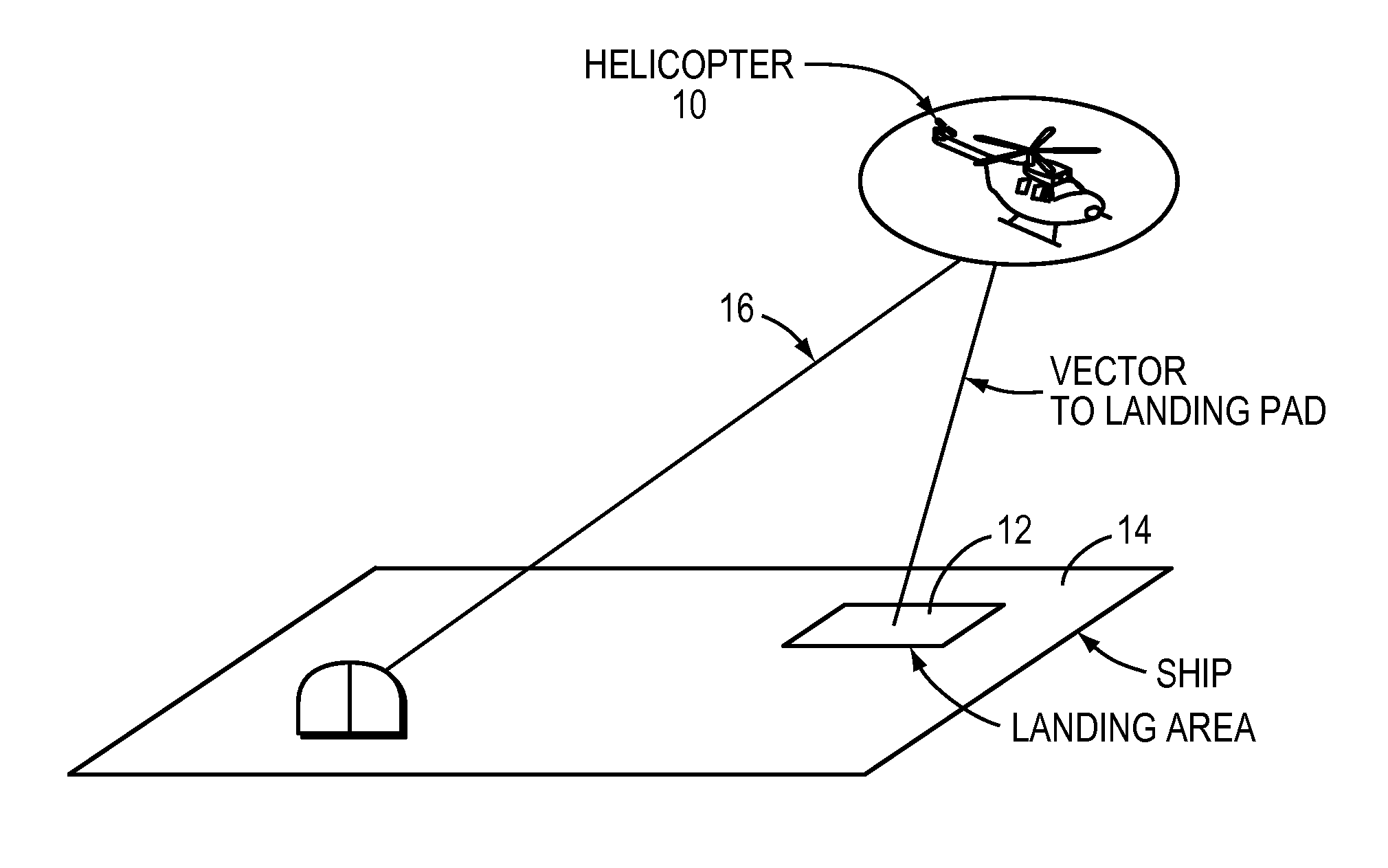
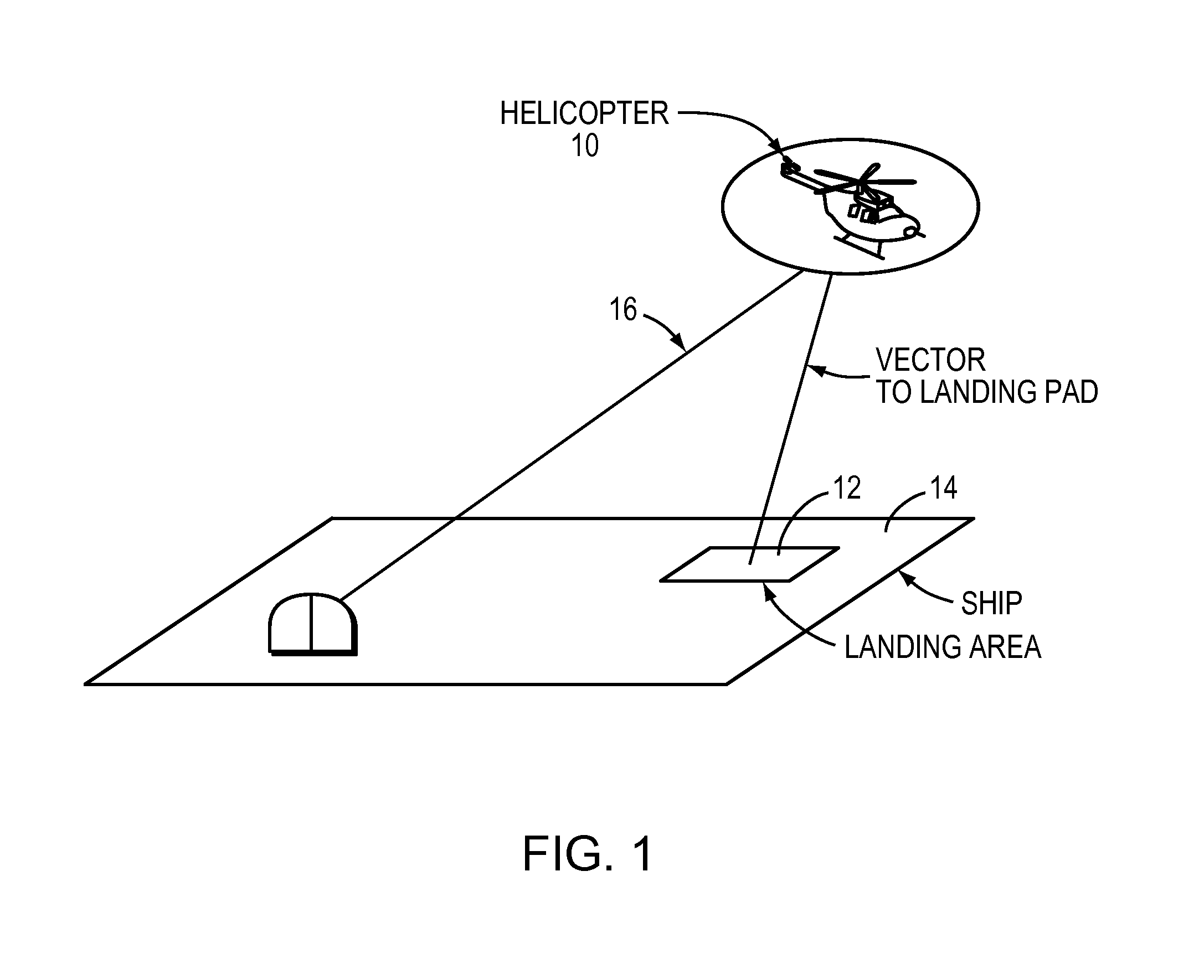
[0024]As shown in FIG. 1, the invention relates to the positioning of an aircraft 10, such as a helicopter, for landing on a designated pad 12 on the deck 14 of a sea going vessel. Both the ship and the aircraft have navigation arrangements described herein and they are provided with a wireless link 16 for transmission of data from the ship to the aircraft.

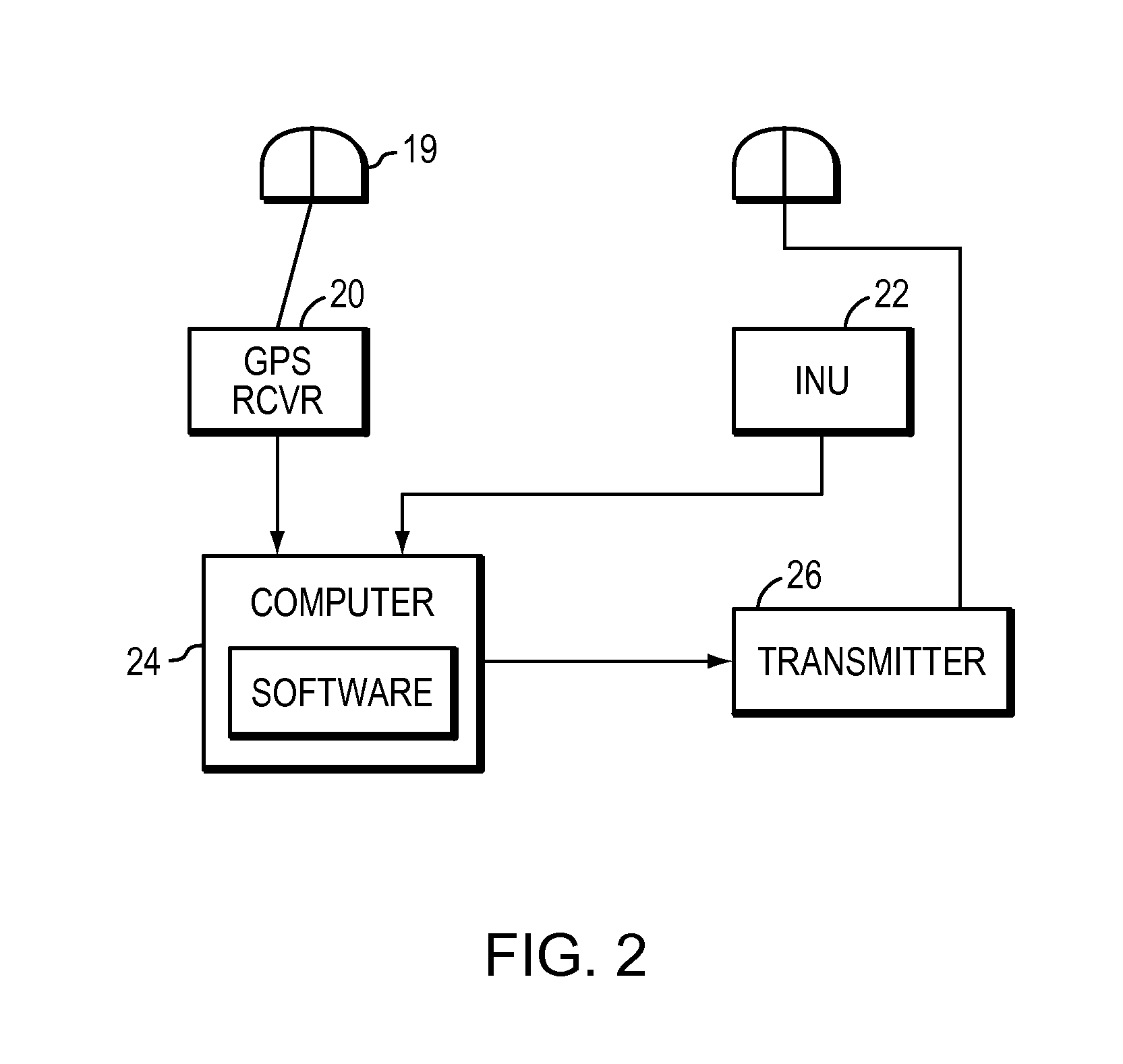
[0025]With reference to FIG. 2, the ship carries a navigation unit 18 comprising a GPS antenna 19, a GPS receiver 20, an inertial navigation unit (INU) 22, a computer 24 and an RTK transmitter 26. The GPS receiver 20 provides position readings but at a rate that is to too low for the operations contemplated by the invention. These readings are used by the computer 24 to update the INU 22, which is subject to long term drift but provides position data at a relatively high rate. An arrangement for integrating an INU with a GPS receiver is described in “OEM4 Inertial: An Inertial / GPS Navigation System on the OEM4 Receiver”, Proceedin...


PUM


Abstract

A system for maneuvering an aircraft for operations in connection with a sea-going vessel, the vessel having a designated area for landings and sling-load operations. Each of the aircraft has a navigation unit (INU) comprising a GPS receiver and an inertial navigation unit. The INU's are updated by data from the GPS receivers and the data from the shipboard unit's GPS receiver and INU are transmitted to the aircraft. The aircraft performs RTK calculations to determine a vector to the shipboard GPS antennas and modifies the vector with data from the INU's.

Description

CROSS-REFERENCE TO RELATED APPLICATIONS[0001]The present application claims the benefit of U.S. Provisional Patent Application Ser. No. 60 / 716,897, which was filed on Sep. 14, 2005, by Thomas J. Ford for a HELICOPTER SHIP BOARD LANDING SYSTEM and is hereby incorporated by reference.BACKGROUND OF THE INVENTION[0002]1. Field of the Invention[0003]This invention relates to the navigation of an aircraft (fixed wing or helicopter) relative to ships at sea.[0004]More specifically, it relates to the takeoff, landing and sling load re-supply operations involving a helicopter and a sea-going vessel.[0005]2. Background Information[0006]Shipboard helicopter operations provide a difficult operational environment. Wind over the deck and wake turbulence shed by the ship super structure offer challenging and unpredictable conditions during takeoff and landing. This is especially true in the operational environment that includes sea-state six, with associated twenty-foot and thirty-three knot winds...

Claims


Application Information

Patent Timeline
Patent Type & Authority Applications(United States)
IPC IPC(8): G06G7/70
CPCG01C21/165G01S19/04G01S19/15G05D1/0684G01C21/28G08G5/0013G08G5/025G01S19/26G05D1/102G05D1/0858
Inventor FORD, TOMBOLOYE, MICHAEL
Owner NOVATEL INC
Why Eureka
Try Eureka