Devices and methods to provide air circulation space proximate building insulation

a technology of air circulation space and building insulation, which is applied in the direction of building repairs, heating types, applications, etc., can solve the problems of leaking water infiltration through the outer skin of the structure into the building frame and insulation, and the space cannot be maintained without a ventilating device,

Inactive Publication Date: 2010-09-16
HETTRICH HANSL
View PDF76 Cites 16 Cited by
  • Summary
  • Abstract
  • Description
  • Claims
  • Application Information

AI Technical Summary

Benefits of technology

[0012]The present disclosure includes devices and system(s) to achieve the ventilation of exterior walls and roofs. Components of the system(s) consider shut-down of the ventilation process when it is not necessary, such as in winter, and in the event of fire, where the prevention of vertical and horizontal fire spread is desired. The present disclosure provides for control of air flow in the event of fire, among other things.

Problems solved by technology

However, with ever-increasing thicker roof insulation required, and dimensional lumber having a nominal maximum depth of 12 inches, that space is impossible to maintain without a ventilating device to maintain a consistent air passage.
Fibrous building envelope insulating materials are dry when installed.
In addition to the aforementioned, leaks permitting water infiltration through the outer skin of the structure into the building frame and insulation such as due to roof and flashing leaks, poorly installed doors, windows, and building wrap and dried and cracked caulking and siding is not uncommon.
Out of necessity and because of exorbitant energy costs to kiln dry lumber, most framing is built from green lumber of species which are fast-growing and including significant moisture.
This retention of moisture not only results in a major consumption of fossil fuels, depleting resources and potentially adding to such climatic issues such as global warming, but adds to the cost of owning, heating and cooling structures.
In more extreme examples, mold supported by excessive moisture can cause respiratory distress and even death due to toxins, for example, by created by fungus growing on the mold.
While roof insulation is not currently directly ventilated, because of its much higher ambient operating temperatures, it probably does expel some acquired moisture because some of the moisture is forced from roof framing cavities as steam under pressure.
No such ventilation exists for wall assemblies and ambient temperatures are lower in walls, likely resulting in little or no expulsion of accumulated water as steam.
Currently, no industry attempts have been made to ventilate exterior walls.

Method used


Image

  • Devices and methods to provide air circulation space proximate building insulation
  • Devices and methods to provide air circulation space proximate building insulation
  • Devices and methods to provide air circulation space proximate building insulation

Examples


Embodiment Construction

[0043]Reference will now be made in detail to the present preferred embodiments of the disclosure, examples of which are illustrated in the accompanying drawings. The method and corresponding steps of the disclosed embodiments will be described in conjunction with the detailed description of the system.

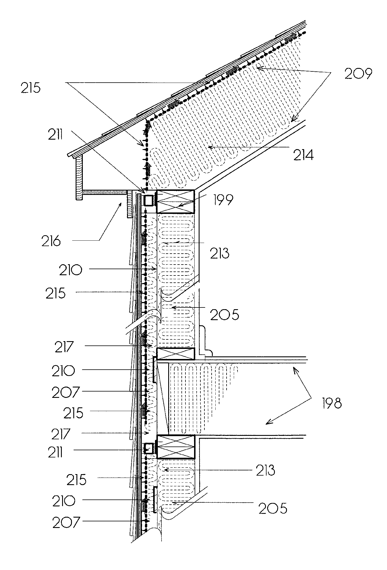
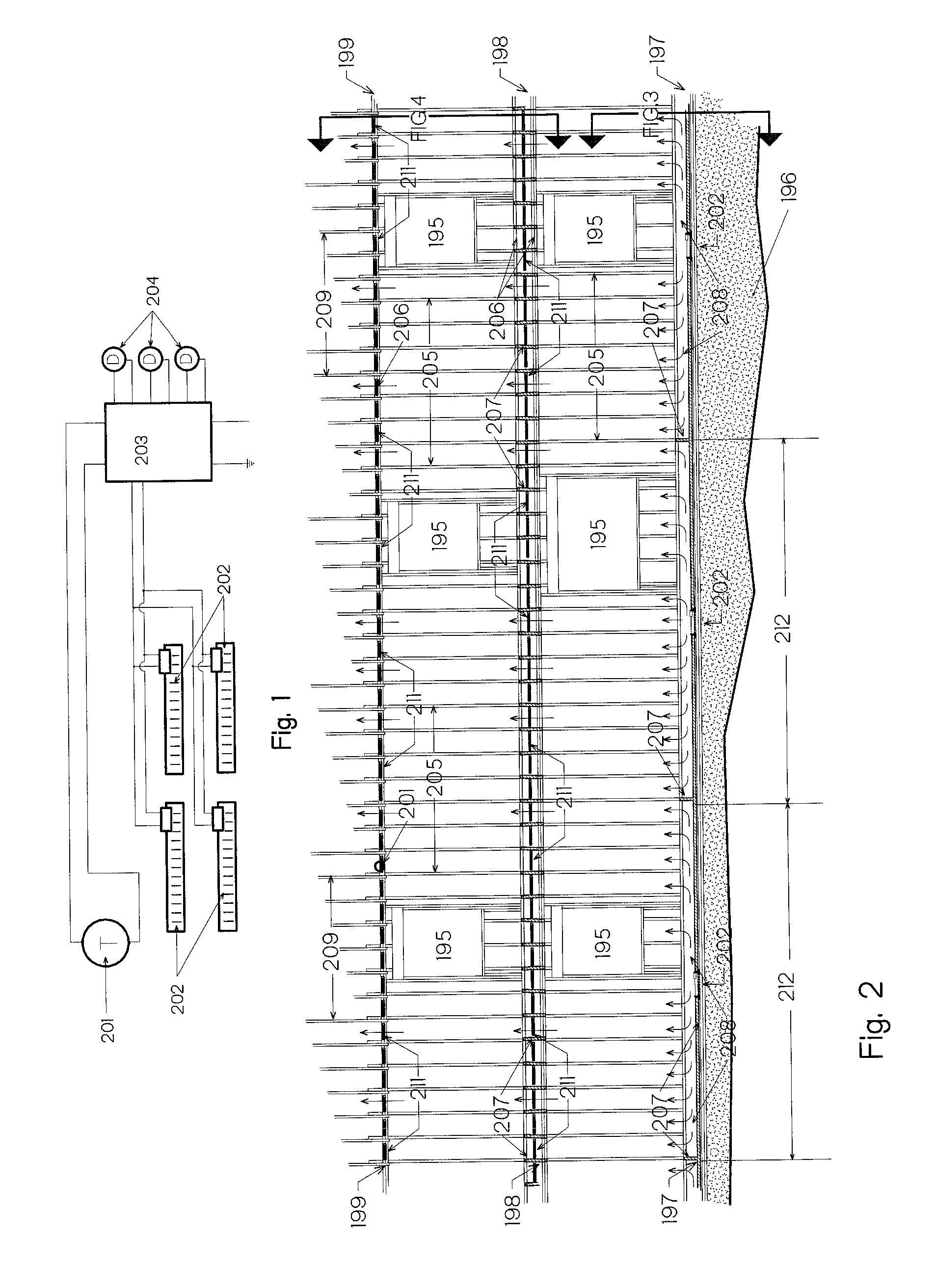
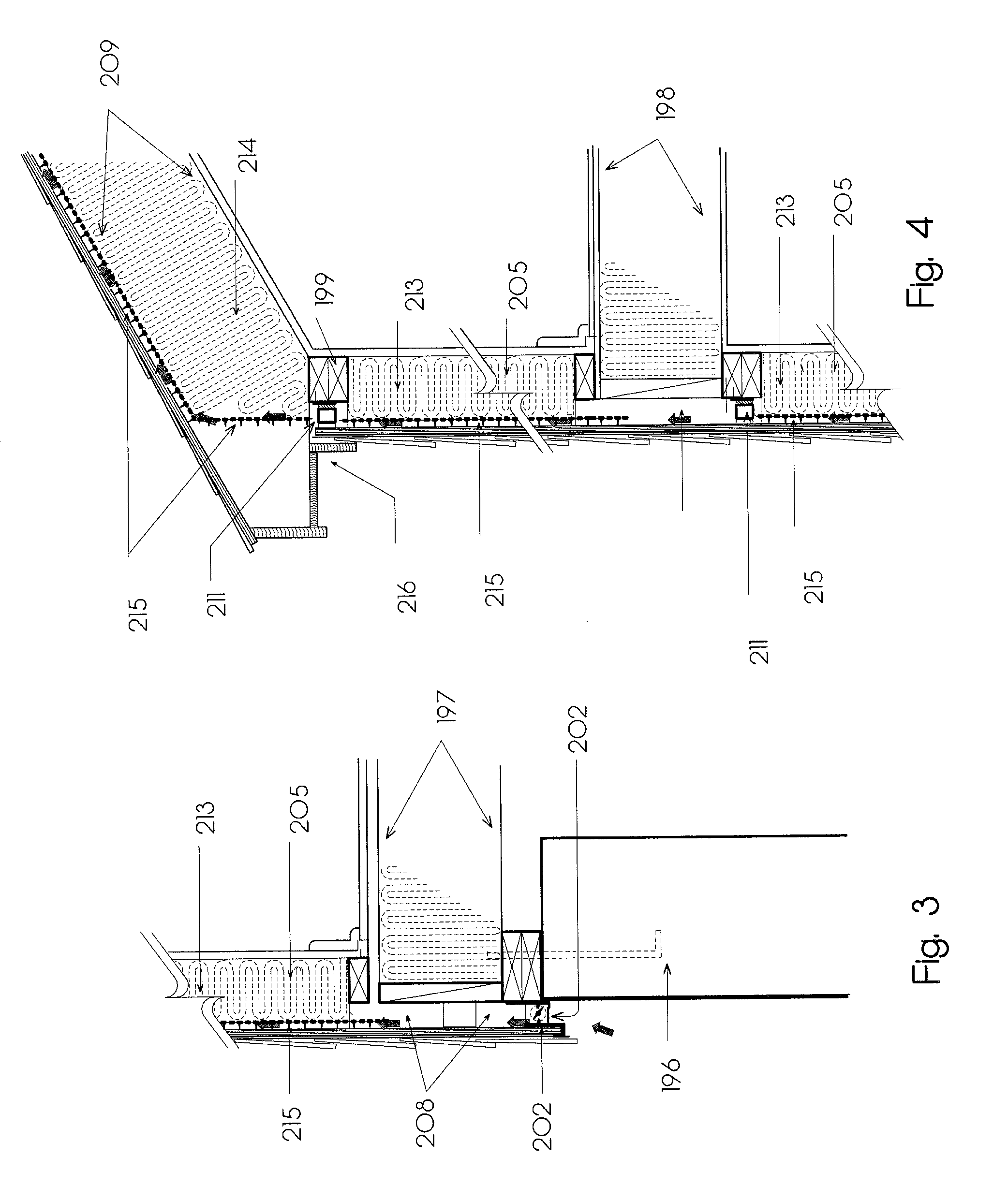
[0044]For purposes of illustration, and not limitation, FIG. 1 is a schematic diagram of an exemplary low voltage control system to control air intake to insulated framing bays. A temperature sensor switch 201 is illustrated which can be located on a roof soffit protected from the elements and direct sunlight. It is preferable to shut-off power to the intake solenoids, 202, when ambient outside temperatures drop below a preset temperature such as 40 degrees F. Closing the cavities to cold air is desirable as cold air is naturally dry, and a static air space would add to the insulating values of the exterior wall assemblies. 203 indicates a central low voltage control unit which ties t...


PUM


Abstract

Devices and associated methods are provided for improving ventilation of insulation material and building construction and renovation. Specifically, the present disclosure includes devices and system(s) to achieve the ventilation of exterior walls and roofs. Components of the system(s) consider shut-down of the ventilation process when it is not necessary, such as in winter, and in the event of fire, where the prevention of vertical and horizontal fire spread is desired.

Description

CROSS-REFERENCE TO RELATED APPLICATIONS[0001]This patent application is a continuation-in-part of U.S. patent application Ser. No. 12 / 649,946, filed Dec. 30, 2009, which is a continuation of U.S. patent application Ser. No. 12 / 139,442, filed Jun. 13, 2008 and issued Feb. 12, 2010 as U.S. Pat. No. 7,654,051, which is a continuation-in-part of and claims priority to U.S. patent application Ser. No. 11 / 203,354, filed Aug. 12, 2005 and issued Dec. 2, 2008 as U.S. Pat. No. 7,458,189, which in turn claims the benefit of priority of U.S. Provisional Patent Application Ser. No. 60 / 634,823, filed Dec. 9, 2004. This patent application is a continuation-in-part of and further claims the benefit of priority to U.S. patent application Ser. No. 12 / 649,946, filed Dec. 30, 2009, which in turn claims the benefit of priority to U.S. patent application Ser. No. 12 / 139,442, filed Jun. 13, 2008, which in turn claims the benefit of priority of U.S. Provisional Patent Application Ser. No. 60 / 943,692, file...

Claims


Application Information

Patent Timeline
Patent Type & Authority Applications(United States)
IPC IPC(8): E04B1/66E04B7/00
CPCE04B1/74E04D13/1625E04D13/17F24F2005/0082F24F5/0075Y02B30/92E04F13/007Y02A30/00Y02B30/90
Inventor POLLACK, ROBERT W.
Owner HETTRICH HANSL
Why Eureka
Try Eureka