Supercharge Your Innovation With Domain-Expert AI Agents!

Particulate matter detection device

Inactive Publication Date: 2010-09-16
NGK INSULATORS LTD
View PDF15 Cites 0 Cited by
  • Summary
  • Abstract
  • Description
  • Claims
  • Application Information

AI Technical Summary

Benefits of technology

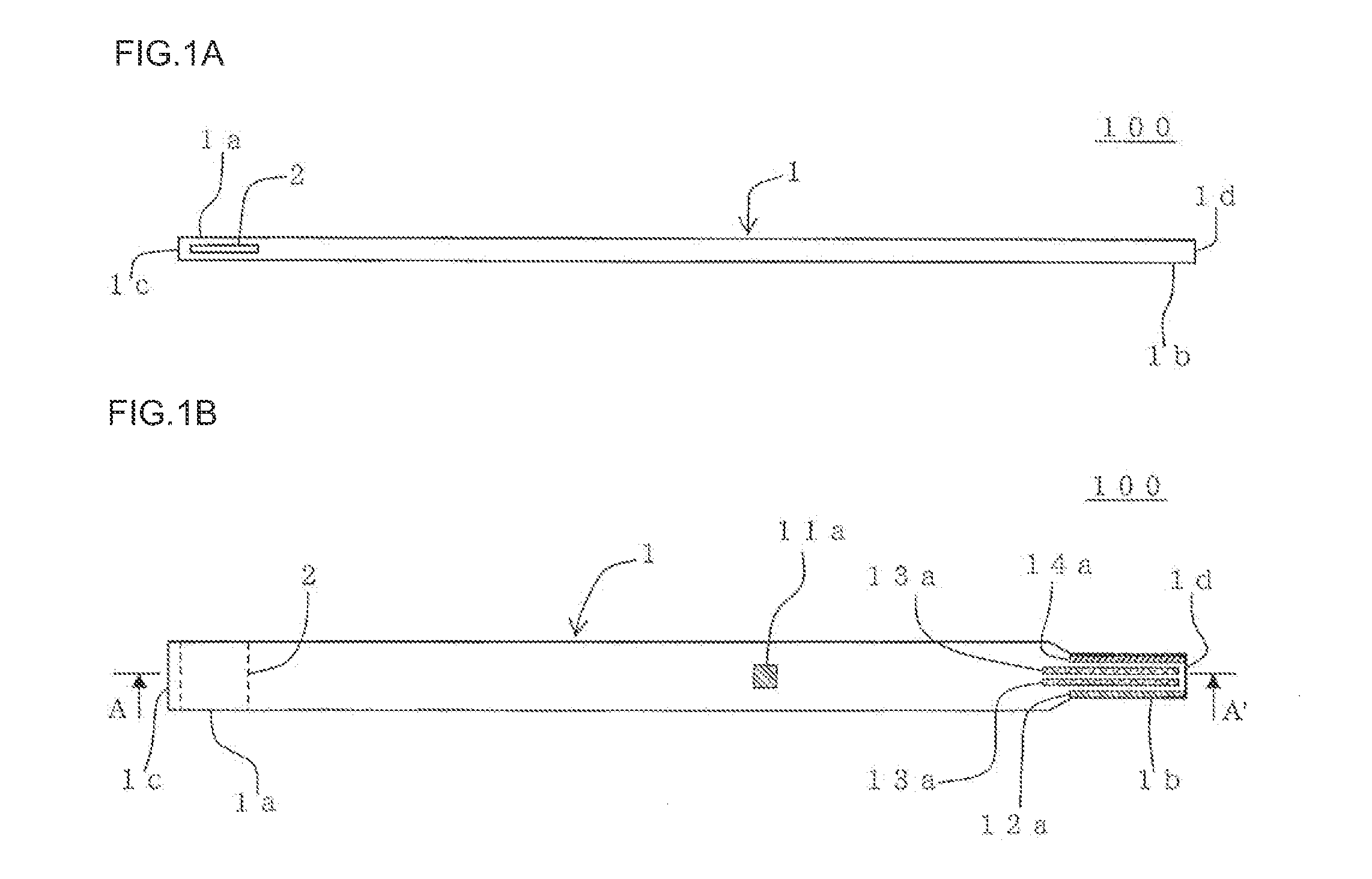
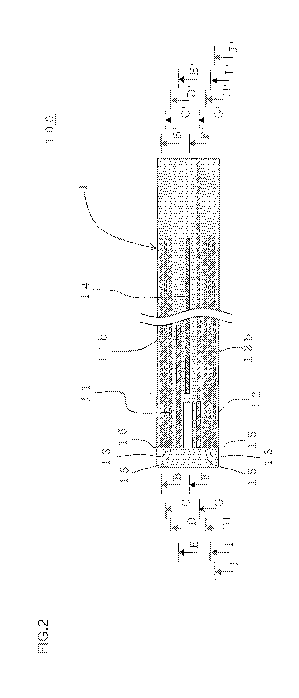
[0005]The present invention was conceived in view of the above problems. An object of the present invention is to provide a particulate matter detection device that has a reduced size, shows only a small measurement error, and can be produced inexpensively.
[0012]Since the heating section is covered with the protective layer that is formed of alumina having a purity of 95% or more, migration of impurities from the dielectric such as alumina to a material that forms the heating section can be effectively prevented, so that a deterioration in the heating section can be suppressed to improve the durability of the heating section.

Problems solved by technology

According to this method, since the ion current due to the charged particulate matter is weak, there has been a problem that a large-scale detection circuit is required for detecting such a weak ion current so that cost increases.
Moreover, since the particulate matter cannot be effectively charged when the exhaust gas flow rate is large, the amount of particulate matter measured may be smaller than the amount of particulate matter actually contained in the exhaust gas.
Therefore, there has also been a problem that a large error occurs.

Method used


Image

  • Particulate matter detection device
  • Particulate matter detection device
  • Particulate matter detection device

Examples


example 1

Preparation of Forming Raw Material

[0132]An alumina pot was charged with alumina as dielectric raw material, polyvinyl butyral as binder, di(2-ethylhexyl) phthalate as plasticizer, sorbitan trioleate as dispersant, and an organic solvent (xylene:butanol=6:4 (mass ratio)) as dispersion medium. The components were mixed to prepare a slurried forming raw material for forming a green sheet. 7 parts by mass of the binder, 3.5 parts by mass of the plasticizer, 1.5 parts by mass of the dispersant, and 100 parts by mass of the organic solvent were used with respect to 100 parts by mass of alumina.

[0133]The slurried forming raw material thus obtained was stirred under reduced pressure to remove bubbles, and the viscosity of the slurried forming raw material was adjusted to 4 Pa·s. The viscosity of the slurry was measured using a Brookfield viscometer.

(Forming Process)

[0134]The slurried forming raw material obtained by the above method was formed into a sheet using a doctor blade method. A cu...


PUM


Abstract

A particulate matter detection device (100) includes a detection device body (1) having at least one through-hole (2) formed at one end of the body (1), a pair of electrodes (11, 12) buried in the wall of the body (1) defining the through-hole (2), and covered with a dielectric, and a heating section (13) disposed in the body (1), and adjusting the temperature of the wall defining the through-hole (2), the heating section (13) being covered with a protective layer (15) formed of alumina having a purity of 95% or more, and the particulate matter detection device allowing a particulate matter contained in a fluid that flows into the through-hole (2) to be electrically adsorbed on the wall surface of the through-hole (2), and detecting the mass of the particulate matter adsorbed on the wall surface by measuring a change in electrical properties of the wall.

Description

BACKGROUND OF THE INVENTION[0001]The present invention relates to a particulate matter detection device. More particularly, the present invention relates to a particulate matter detection device that has a reduced size, shows only a small measurement error, and can be produced inexpensively.[0002]A flue exhaust gas or a diesel engine exhaust gas contains a particulate matter (PM) such as soot or the like and has been a cause for air pollution. A filter (diesel particulate filter: DPF) made of a ceramic or the like has been widely used to remove the particulate matter. The ceramic DPF can be used for a long period of time, but may suffer defects such as cracks or erosion due to thermal deterioration or the like, so that a small amount of particulate matter may leak from the DPF. It is very important to immediately detect such occurrence of the defects and to recognize the abnormality of a device from the viewpoint of preventing air pollution.[0003]Such defects may be detected by prov...

Claims


Application Information

Patent Timeline
IPC IPC(8): G01N37/00
CPCG01N15/0656G01N27/60G01N27/043G01N27/68
Inventor TOKUDA, MASAHIROKONDO, ATSUOSAKUMA, TAKESHIEGAMI, TAKASHI
Owner NGK INSULATORS LTD
Features
  • R&D
  • Intellectual Property
  • Life Sciences
  • Materials
  • Tech Scout
  • Unparalleled Data Quality
  • Higher Quality Content
  • 60% Fewer Hallucinations
Learn More