Tube-fin type heat exchange unit with high pressure resistance

a heat exchange unit and tube-fin technology, applied in the field of tube-fin heat exchange units with high pressure resistance, can solve the problems of low heat exchange efficiency, small heat exchange area, and large volume, and achieve high heat exchange efficiency, large heat transfer surface, and high pressure resistance

Inactive Publication Date: 2010-09-16
NANNING BALING TECHNOLOGY CO LTD
View PDF8 Cites 14 Cited by
  • Summary
  • Abstract
  • Description
  • Claims
  • Application Information

AI Technical Summary

Benefits of technology

[0005]The present invention is to provide a tube-fin type heat exchange unit with high pressure resistance, in order to solve the above-described problems, wherein the heat exchange unit of the present invention has a large heat transfer surface, high heat exchange efficiency and high pressure resistance.

Problems solved by technology

Although such types of heat exchange units are able to work under high pressure, the surface heat transfer areas thereof are small and the heat exchange efficiency thereof is low.
In order to obtain satisfactory heat exchange efficiency, such heat exchange units must have large volume, which results in huge volume, heavy weight, high cost and high energy consumption of the heat exchangers.
Although such heat exchange units have large surface heat transfer areas and high heat exchange efficiency, they could not work under the pressure over 0.4 Mpa.
So they could not be used in heat exchanger equipments which have high working pressure, such as oil coolers, water heaters, steam boilers and so on.
However, there exists a relationship of powder series between the pressure drawdown and the flow rate in foam metal, such compact heat exchange units could only be used in the case of low flow rate for the high flow resistance thereof.
Further, the foam metal is easily blocked and has high requirement for environmental cleanliness, which restricts the application thereof.

Method used


Image

  • Tube-fin type heat exchange unit with high pressure resistance
  • Tube-fin type heat exchange unit with high pressure resistance
  • Tube-fin type heat exchange unit with high pressure resistance

Examples


Embodiment Construction

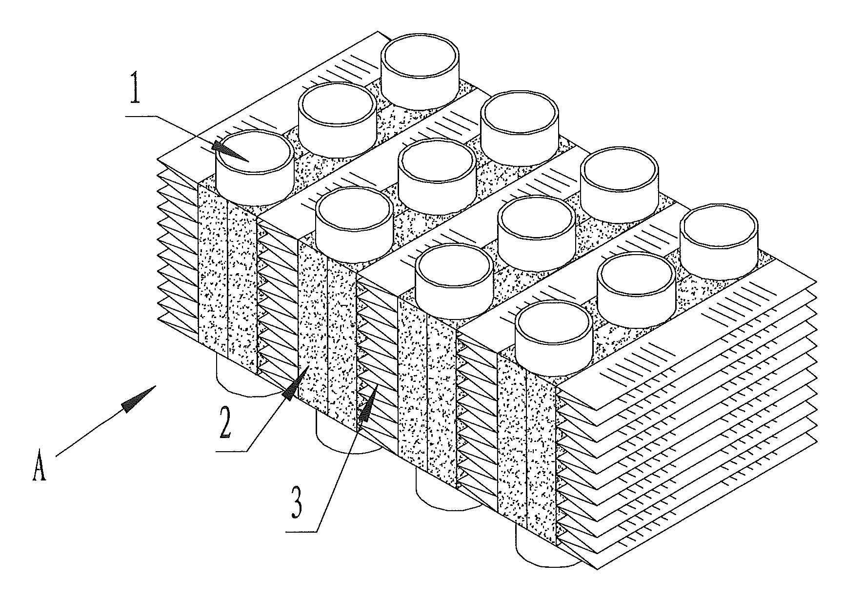
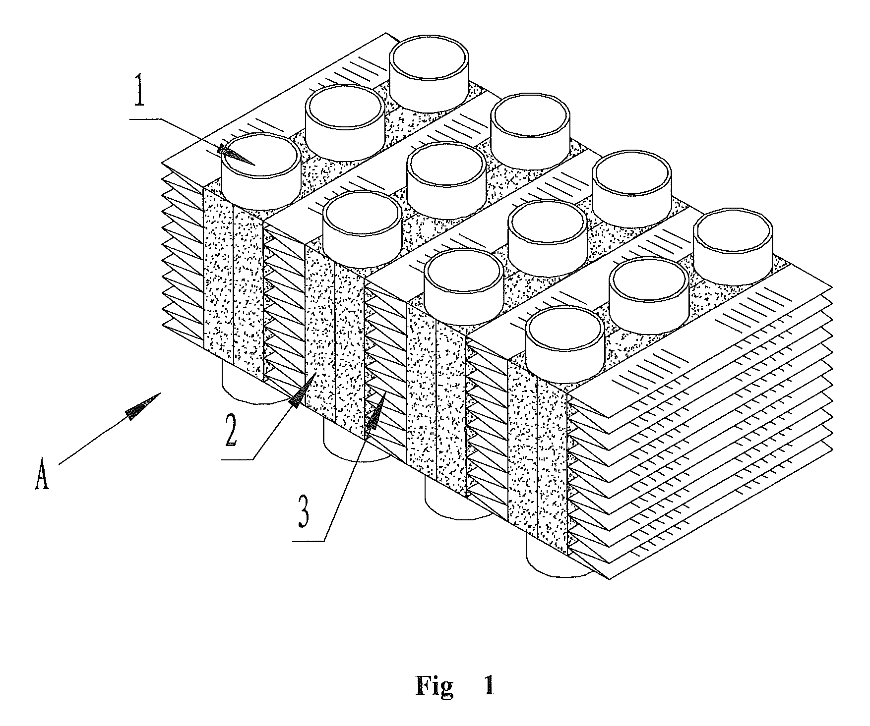
[0011]The present invention will be described further referring to the accompanying drawings and the embodiments.

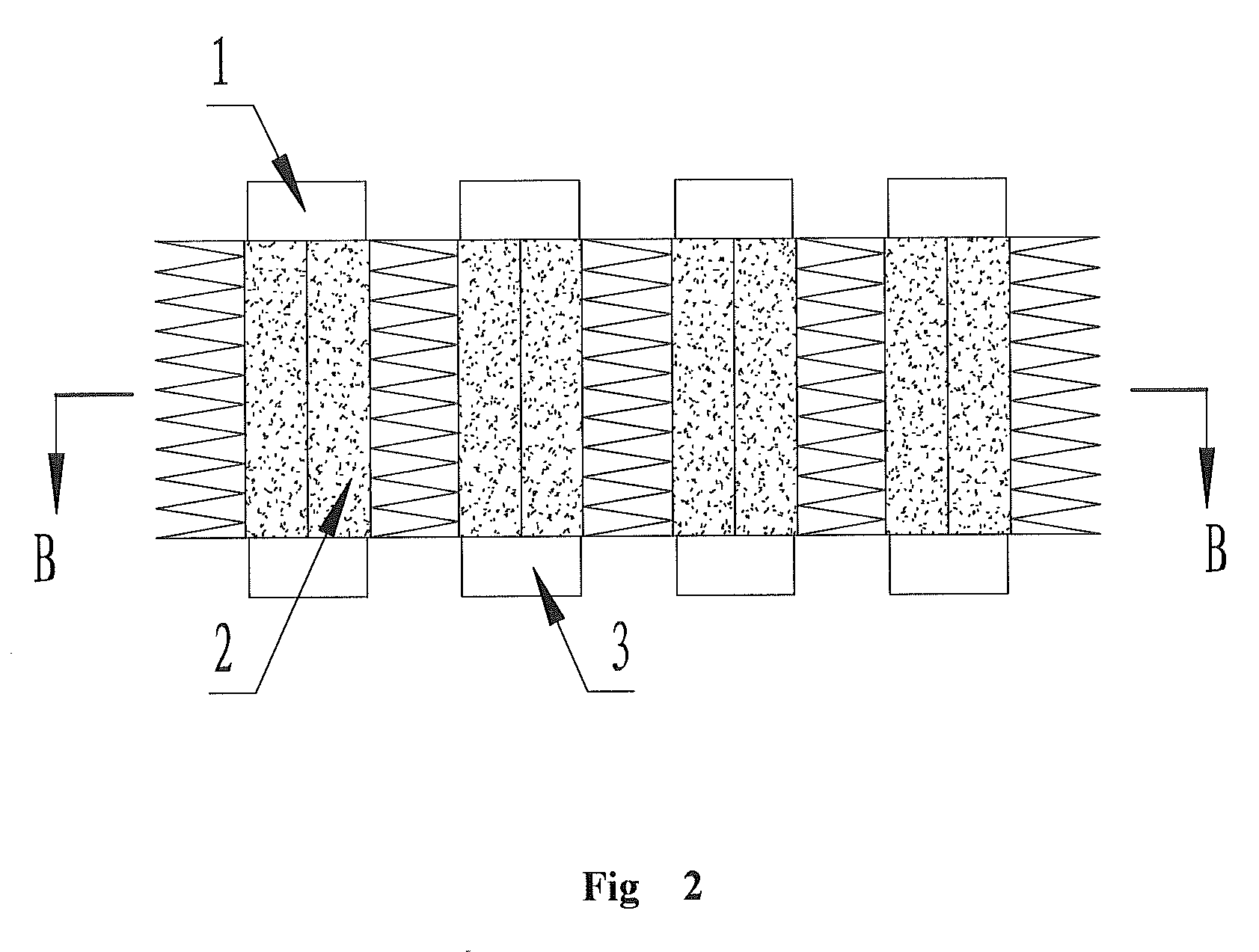
[0012]Referring to FIG. 1, the tube-strip type heat exchange unit with high pressure resistance of the present invention comprises a plurality of tubes (1), foam metal (2) and a plurality of heat dissipation fins (3). Tubes (1) and heat dissipation fins (3) are spaced arranged. Foam metal (2) is located in the interspace between tubes (1) and the superface of heat dissipation fins (3). Solder is disposed between tubes (1) and foam metal (2), and between foam metal (2) and heat dissipation fins (3). So tubes (1), foam metal (2) and heat dissipation fins (3) are jointed by soldering to form the heat exchange unit.

[0013]In details, the diameter and wall thickness of tubes (1) could be modified according to the volume and pressure resistance requirement for the heat exchange unit. Tubes (1) could be arranged in a single line or in multiple lines, depending on the thickness re...


PUM


Abstract

The present invention disclosed a tube-fin type heat exchange unit with high pressure resistance, wherein said heat exchange unit comprises a plurality of tubes, foam metal and a plurality of heat dissipation fins; said tubes and said heat dissipation fins are spaced arranged; said foam metal is located in the interspace between said tubes and the superface of said heat dissipation fins; and solder is disposed between said tubes and said foam metal, and between said foam metal and the superface of said heat dissipation fins to make a firm connection. The heat exchange unit of the present invention has good heat exchange performance, high pressure resistance and small volume, so it is suitable for volume production and could be widely applied in heat exchangers for vehicle, industry and civil use.

Description

FIELD OF THE INVENTION[0001]The present invention relates generally to a heat exchanger for vehicle, industry and civil use, and more specially relates to a tube-fin type heat exchange unit with high pressure resistance.BACKGROUND OF THE INVENTION[0002]The general high-pressure resistant heat exchangers use filmed tubes, ribbed tubes or tube bundles as core heat exchange units. Although such types of heat exchange units are able to work under high pressure, the surface heat transfer areas thereof are small and the heat exchange efficiency thereof is low. In order to obtain satisfactory heat exchange efficiency, such heat exchange units must have large volume, which results in huge volume, heavy weight, high cost and high energy consumption of the heat exchangers.[0003]The general compact heat exchangers use tube-fin type heat exchange units as core heat exchange units. Although such heat exchange units have large surface heat transfer areas and high heat exchange efficiency, they co...

Claims


Application Information

Patent Timeline
Patent Type & Authority Applications(United States)
IPC IPC(8): F28F1/24
CPCF28F13/003F28F1/126
Inventor LUO, QINWEI, YUANHAI
Owner NANNING BALING TECHNOLOGY CO LTD
Why Eureka
Try Eureka