Storage combination boiler

a combination boiler and storage technology, applied in the field of storage combination boilers, can solve the problems of prolonging the life of the dchp unit and maximising heat and power generation efficiency, and achieve the effect of reducing the temperature change rate and being advantageously controlled

Inactive Publication Date: 2010-09-16
MICROGEN ENGINE CORP HLDG BV
View PDF8 Cites 13 Cited by
  • Summary
  • Abstract
  • Description
  • Claims
  • Application Information

AI Technical Summary

Benefits of technology

[0015]The storage vessel preferably causes the fluid stored within the storage vessel to have a rate of change of temperature substantially less than the rate of change of temperature of the fluid in the first piping system without the storage vessel. The storage vessel may be of a sufficient volume so as to cause this to be the case. Optionally, the volume of the storage vessel is 100 litres. The use of a storage vessel may decrease the rate of change of temperature by at least 10%, preferably 50% and optionally approximately 100%.
[0016]The first piping system preferably comprises a piping circuit. Advantageously, the first piping system also comprises: a second piping circuit; and a valve, configured to cause the first fluid either to flow around the first piping circuit or to flow around the second piping circuit. This allows the provision of hot water on demand without central heating. In the preferred embodiment, the storage vessel is located in the first piping circuit. In the preferred embodiment, the second piping circuit is a central heating piping network and the fluid in the first piping system is a central heating fluid. By so doing, the dchp unit can be advantageously controlled without any effect from the central heating system.

Problems solved by technology

This prolongs the lifetime of the dchp unit, whilst maximising heat and power generation efficiency.

Method used


Image

  • Storage combination boiler
  • Storage combination boiler
  • Storage combination boiler

Examples


Embodiment Construction

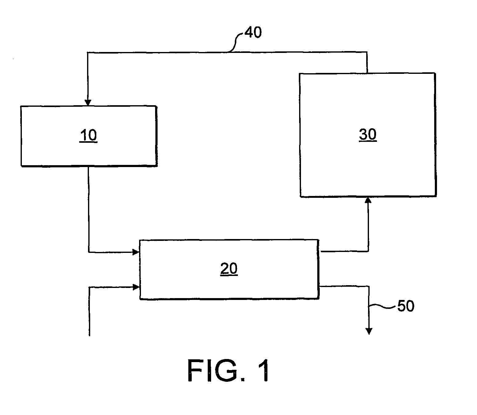
[0027]Referring first to FIG. 1, there is shown a schematic block diagram of a storage combination boiler according to the present invention. The storage combination boiler comprises an engine 10, a heat exchanger 20, and a storage vessel 30.

[0028]The engine 10 is arranged to provide a heat output, and is also used to generate an electricity output. Water, travelling through a first circuit 40, is heated by the engine 10, the heated water then flows through a heat exchanger 20. A second water supply 50 also passes through the heat exchanger 20, which causes the second water supply 50 to be heated by the water flowing through the first circuit. The water flowing out of the heat exchanger 20 on the first circuit then flows into a storage vessel 30. The storage vessel 30 is of sufficient volume such that water flowing through the storage vessel 30 remains within the storage vessel for a significant period of time before flowing out of the storage vessel 30 and flowing back towards the ...


PUM


Abstract

A storage combination boiler system and a method for providing heating, comprising: a domestic combined heat and power (dchp) unit, which provides a heat output and an electricity output; a first piping system, containing fluid which is heated by the heat output of the dchp unit; a second piping system, containing fluid which is heated by transfer of heat from the fluid in the first piping system using a heat exchanger; and a storage vessel, located within the first piping system, downstream from the heat exchanger, for receiving and storing fluid within that first piping system so as to provide a thermal store for the heat in the first piping system.

Description

TECHNICAL FIELD[0001]This invention relates to a storage combination boiler using a domestic combined heat and power (dchp) unit to provide heating and hot water supply to meet user requirements, without the need for an external tank to store hot water.BACKGROUND TO THE INVENTION[0002]An advantage of dchp units is their ability to provide heating, hot water and electrical power to a household with a single engine, thereby giving a high overall efficiency. For example, our International Patent Application, WO-A-03 / 084023, describes such a dchp unit that comprises a Stirling engine generator.[0003]The electricity output can be used either when the household demands electricity or it may be sold back into the electrical grid supplying the household. Hence, the net amount of electricity drawn from the grid can be reduced. The electrical power output of a dchp unit will depend on the generating capacity of its engine, which will be fixed for a specific unit, and the length of time for wh...

Claims


Application Information

Patent Timeline
Patent Type & Authority Applications(United States)
IPC IPC(8): G05D23/00F24H9/20F24D18/00
CPCF02G2254/10Y02E20/14F24H2240/04F24H1/00F24D18/00F24D2103/17F24D2103/13F24D2101/80F02G1/043F24D3/082F24D11/002F24H1/52
Inventor CLARK, DAVIDSTEADE, DAVID
Owner MICROGEN ENGINE CORP HLDG BV
Why Eureka
Try Eureka