Microwave system for driving a linear accelerator

a linear accelerator and microwave technology, applied in accelerators, electric discharge tubes, magnetrons, etc., can solve the problems of 3,000 operating hours, relatively short lifespan of magnetrons, and low power levels of klystrons, so as to increase efficiency and dependability, and achieve higher energy and power outputs.

Inactive Publication Date: 2010-09-16
LEEK PAUL H
View PDF6 Cites 16 Cited by
  • Summary
  • Abstract
  • Description
  • Claims
  • Application Information

AI Technical Summary

Benefits of technology

[0007]The present invention satisfies this need by providing a microwave system for driving a linear accelerator that employs a plurality of magnetrons. More specifically, the inventive system, which offers, among other things, increased magnetron life and improved system reliability, comprises: a plurality of magnetrons; at least one pulse generator to energize the magnetrons; means for synchronizing the frequency and phase of outputs from the magnetrons; and at least one waveguide for transmitting the synchronized outputs or power from the magnetrons to the linear accelerator.
[0018]The present invention also provides a radiation (i.e., electron, x-ray) source comprising a linear accelerator, and connected thereto, a microwave system, as described herein above. The inventive radiation source offers increased efficiency and dependability, higher energy and power outputs, as well as, different energy outputs that can take the form of successive pulses that can alternate between at least two different energy levels.
[0027]FIG. 4 is a simplified plan view of yet another preferred embodiment of the radiation source of the present invention where each magnetron in a magnetron pair is provided with a high power pulse generator having a pulse forming network or PFN thereby facilitating “energy hopping” or “energy jumping”;

Problems solved by technology

Power levels, however, are not as high as those offered by klystrons.
In addition, magnetrons have a relatively short lifespan (i.e., 3,000 operating hours), cannot easily be rebuilt, and their self-oscillation operation is affected by feedback, especially from highly reactive loads.
Tube operation is relatively quiet electrically, but efficiency is low.
While these tubes can be rebuilt and offer a relatively long lifespan of up to 20,000 operating hours, they are large and heavy and require a large solenoid.
In addition, these tubes are relatively expensive and are not readily available, in some cases requiring delivery times of greater than one or two months.

Method used


Image

  • Microwave system for driving a linear accelerator
  • Microwave system for driving a linear accelerator
  • Microwave system for driving a linear accelerator

Examples


Embodiment Construction

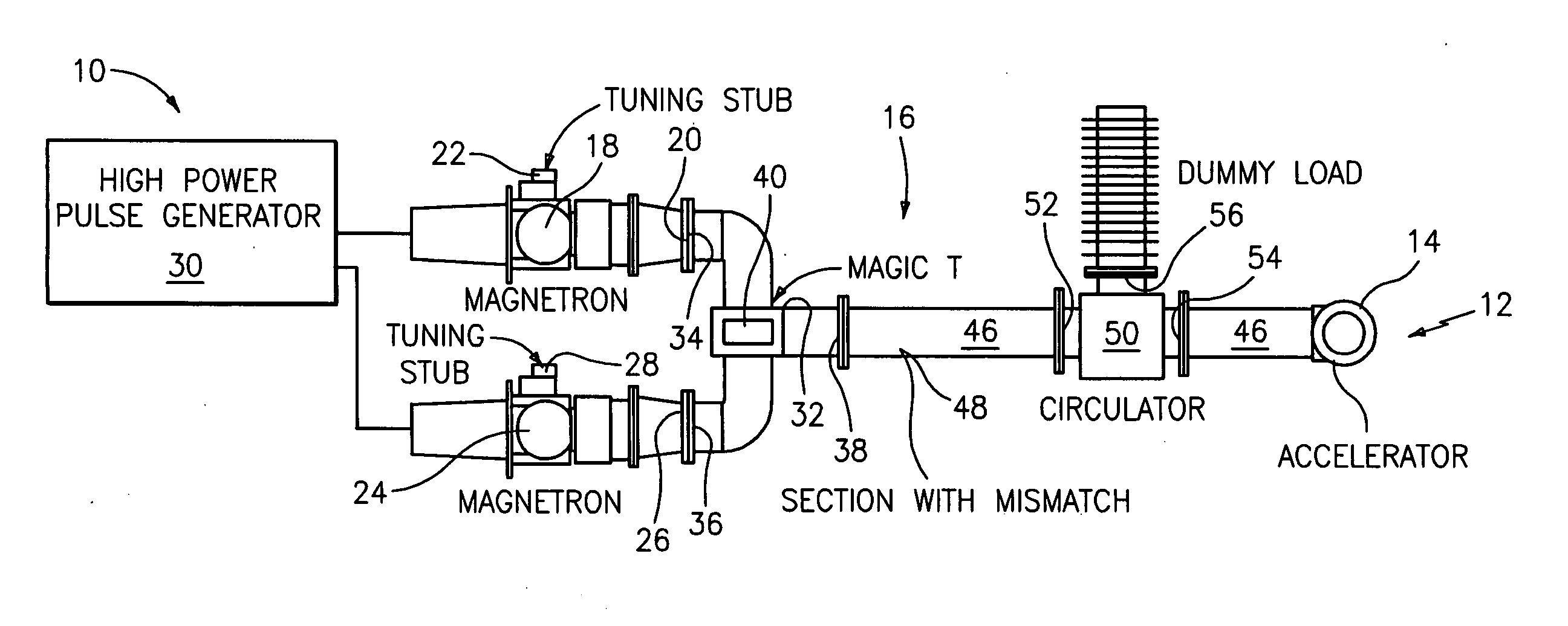
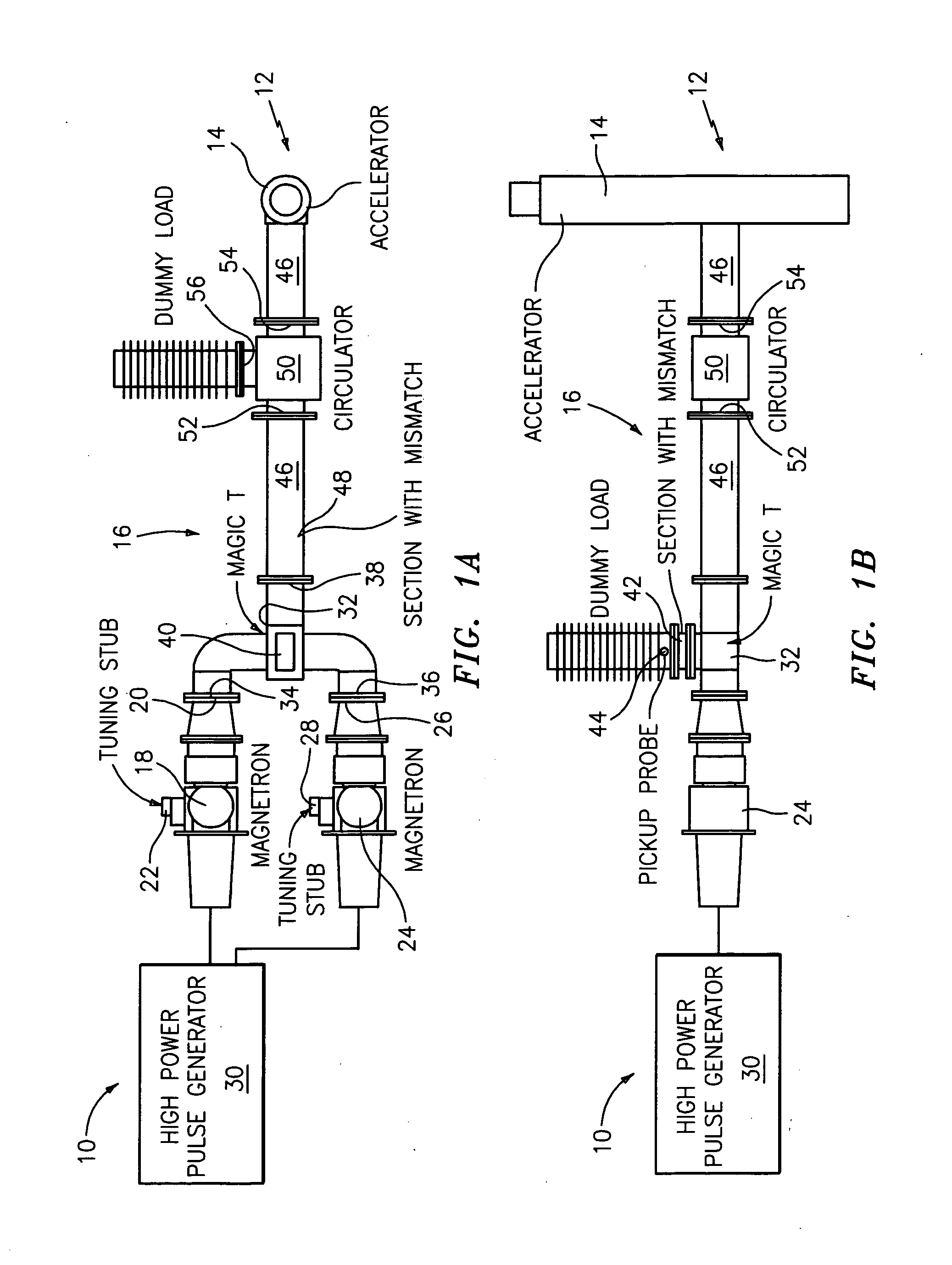
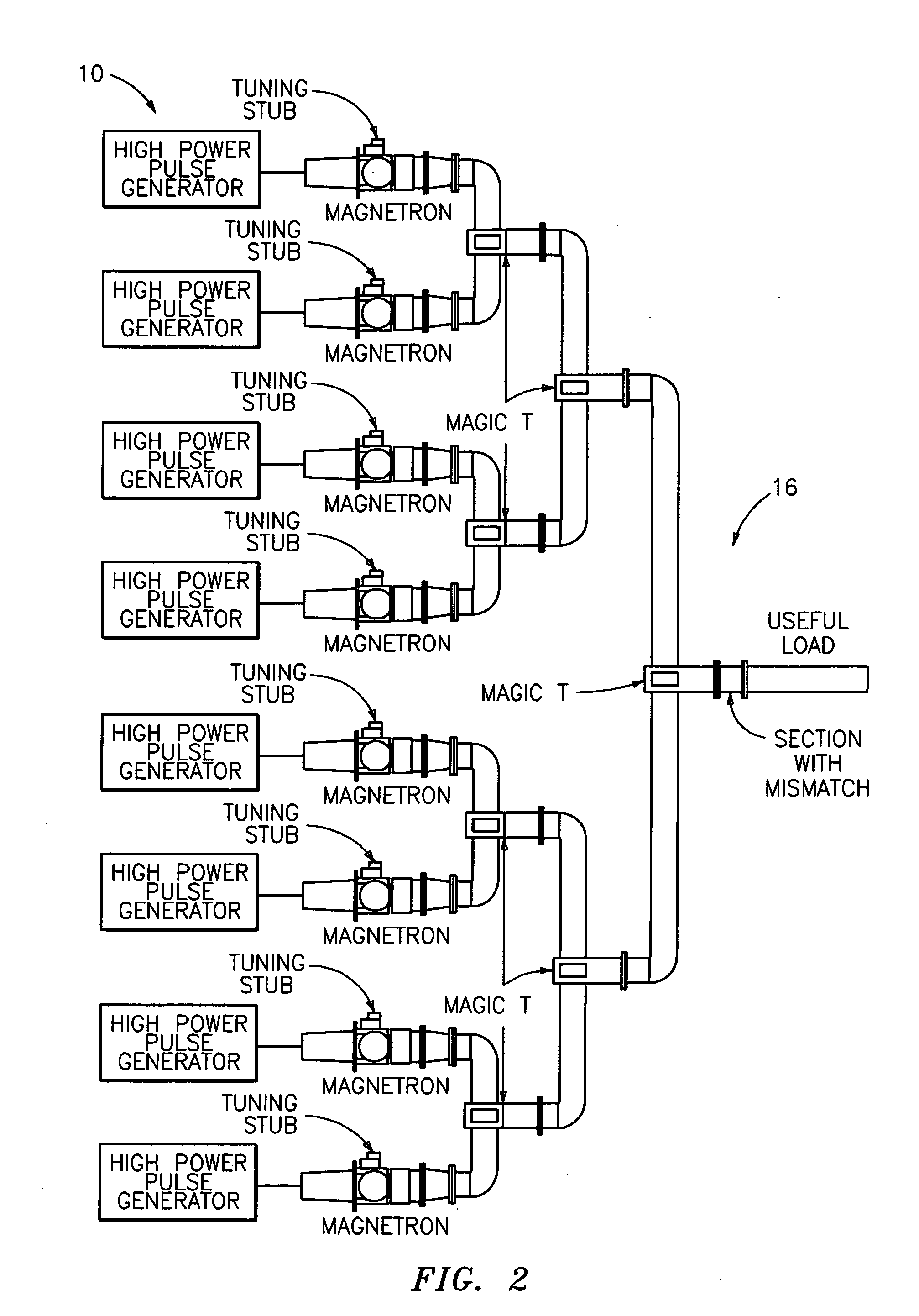
[0030]As noted above, it has been discovered by way of the present invention that linear accelerators driven by several smaller, less expensive magnetrons can provide higher energy and higher power outputs. It has also been discovered that these accelerators can produce different energy outputs, and that these outputs can be made to “jump” from one energy level to another.

[0031]Furthermore, the microwave system of the present invention serves to increase linear accelerator efficiency. Accelerator efficiency (Q) is equal to the quotient of electron beam power (Pb) divided by total power (Pt) [Q=Pb / Pt]. In most applications, Pb is about ½ of Pt, for an efficiency of 50%. By way of the present invention, Pb can increase to about ¾ of Pt, for an efficiency of 75% or more.

[0032]An increase in the operational life of magnetrons is also achieved using the microwave system of the present invention. Most accelerator applications operate with the magnetron at or close to maximum output peak p...


PUM


Abstract

A microwave system for driving a linear accelerator is provided. The inventive microwave system employs a plurality of magnetrons, at least one pulse generator to energize the magnetrons, means for synchronizing outputs from the magnetrons, and at least one waveguide for transmitting synchronized outputs or power from the magnetrons to a linear accelerator. The linear accelerator that is driven by the inventive microwave system demonstrates increased efficiency and dependability, higher energy and power outputs, as well as, different energy outputs that can take the form of successive pulses that alternate between at least two different energy levels.

Description

RELATED APPLICATION[0001]This application claims priority from U.S. Provisional Patent Application Ser. No. 60 / 751,570, filed Dec. 20, 2005, which is herein incorporated by reference in its entirety.TECHNICAL FIELD[0002]The present invention generally relates to a microwave system for driving a linear accelerator, and more particularly relates to a microwave system that employs a plurality of magnetrons.BACKGROUND AND SUMMARY OF THE INVENTION[0003]Linear accelerators require power in the form of high power pulses of short duration. This form of power can be supplied by either a magnetron or a klystron.[0004]Magnetrons are relatively high efficiency, self-oscillating, diode-type electron tubes that are used to produce microwave energy. These electron tubes, which are typically small, light weight and relatively inexpensive, with some models being readily available for purchase, offer peak power levels of up to 5 megawatts (MW) and average power levels of about 10 kilowatts (kW). Powe...

Claims


Application Information

Patent Timeline
Patent Type & Authority Applications(United States)
IPC IPC(8): H05H9/00H01J25/50
CPCH05H9/00H05H7/00
Inventor LEEK, PAUL H.
Owner LEEK PAUL H
Why Eureka
Try Eureka