System and method for monitoring of welding state

a technology of state monitoring and welding pipe, which is applied in the field of system for monitoring the state of production of electric resistance welding pipe, can solve the problems of inability to obtain an image with a sufficient resolution, inability to grasp the heat input state (molten state), of the weld face, and inability to obtain images of parts (clearance) between the fibers forming the fiber scope, etc., to achieve high precision, easy to understand format, and high precision analysis

Active Publication Date: 2010-09-16
NIPPON STEEL CORP
View PDF2 Cites 17 Cited by
  • Summary
  • Abstract
  • Description
  • Claims
  • Application Information

AI Technical Summary

Benefits of technology

[0039]Due to the present invention, the following effects are obtained. That is, it is possible to obtain a high definition image of light emitted from welded parts of steel plate formed into a tube shape so as to produce electric-resistance-welded pipe, possible to convert this to image data for analysis and display, and thereby possible to perform high precision analysis and display the results in a more easily understandable format by image processing or data processing. The results of this high precision analysis and easily understandable display enable higher precision, better response control, contribute to stable quality and improved productivity, and also remarkably improve the work efficiency of the operators and the monitoring ability.
[0040]Fu

Problems solved by technology

Therefore, there was the problem that it was extremely difficult to obtain a grasp of the heat input state (molten state), including the butting state, of the weld faces.
Further, in the technology described in Japanese Patent Publication (A) No. 62-203680, a fiber scope was used to obtain an image, so it was not possible to obtain an image with

Method used


Image

  • System and method for monitoring of welding state
  • System and method for monitoring of welding state
  • System and method for monitoring of welding state

Examples


first embodiment

[0066]Below, a first embodiment of the present invention will be explained while referring to the drawings.

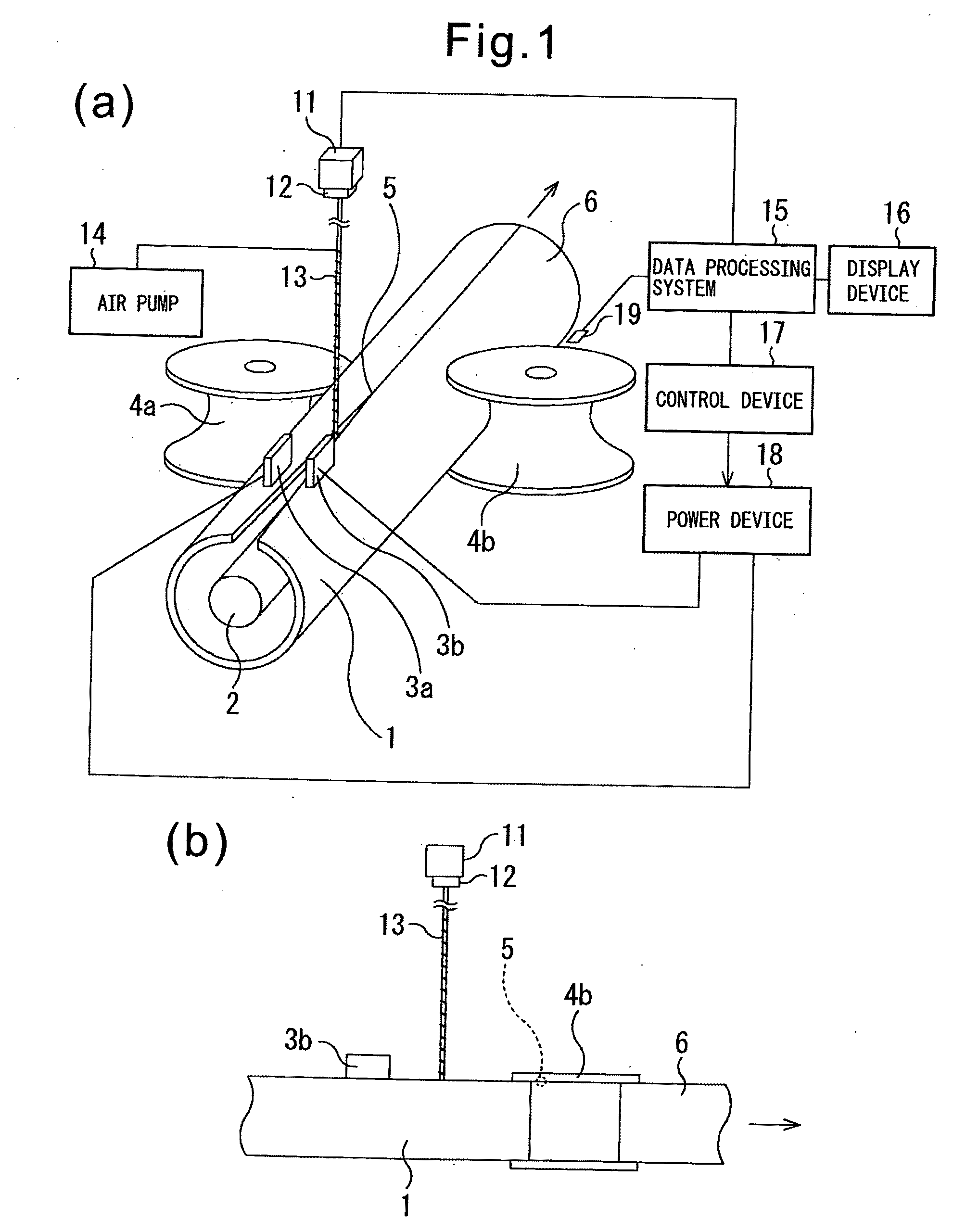
[0067]FIG. 1 are views showing an electric-resistance-welded pipe production line (electric-resistance-welded pipe production system). Further, in FIG. 1, for convenience in explanation, part of the configuration of the electric-resistance-welded pipe production line is omitted. Further, FIG. 1(a) is a perspective view, while FIG. 1(b) is a view of FIG. 1(a) seen from the horizontal direction. Further, in FIG. 1, it is assumed that the strip-shaped steel plate 1 progresses in the arrow direction (in FIG. 1(a), the direction from the front to rear, while in FIG. 1(b), the direction from left to right).

[0068]In the electric-resistance-welded pipe production line, the two ends of a strip-shaped steel plate 1 are forced together by using a not shown plurality of rolls to form the strip-shaped steel plate 1 into a tube shape. FIG. 1 show the state after the strip-shaped steel plate ...

second embodiment

[0150]Next, a second embodiment of the present invention will be explained. In the present embodiment, in addition to the configuration explained in the above first embodiment, image data obtained by capturing the welded parts 5 of the tube-shaped steel strip 1 from directly above them is also used to analyze the state of the welded parts 5 of the tube-shaped steel strip 1. In this way, the present embodiment adds to the above first embodiment the configuration for capturing an image of the welded parts 5 of the tube-shaped steel strip 1 from directly above them and processing it. Therefore, in the explanation of the present embodiment, parts the same as in the above first embodiment are assigned the same reference numerals as the reference numerals assigned to FIG. 1 to FIG. 16 and detailed explanations are omitted.

[0151]FIG. 17 is a view showing an example of the configuration of an electric-resistance-welded pipe production line (electric-resistance-welded pipe production system)...

third embodiment

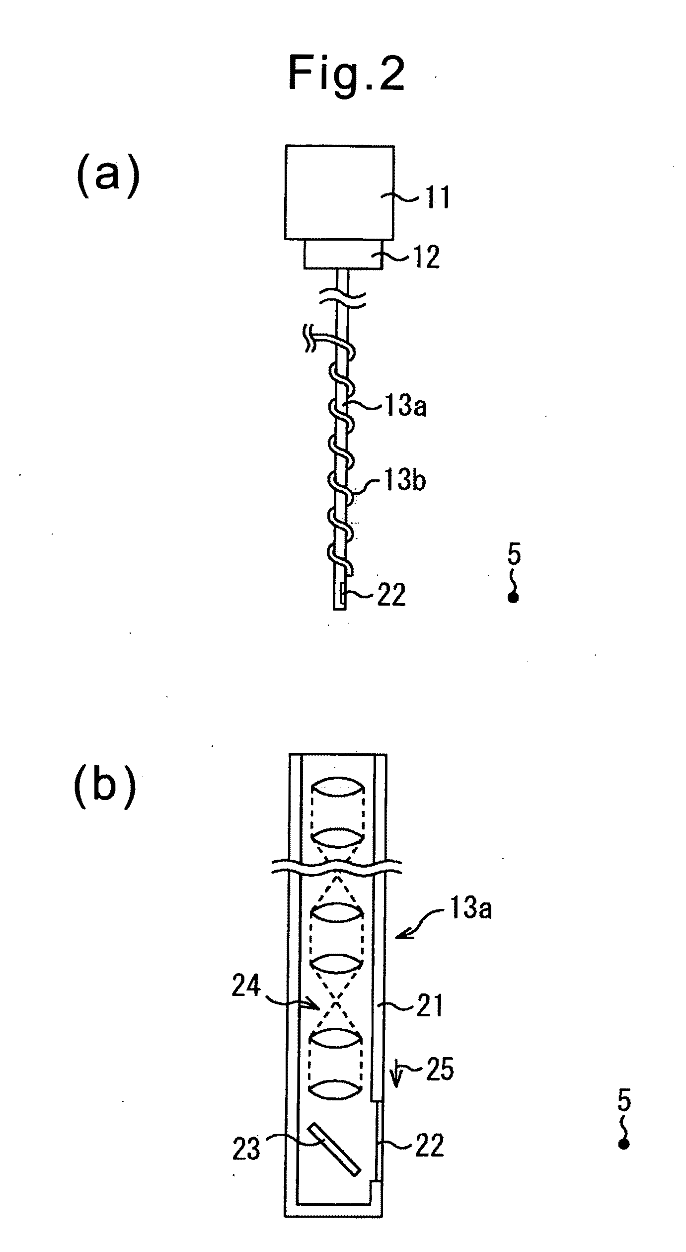
[0155]Next, a third embodiment of the present invention will be explained. In the above first and second embodiments, the mirror 23 was provided inside the container 21 of the relay lens unit 13. As opposed to this, in the present embodiment, the explanation will be given of the case of forming the relay lens unit without providing a mirror 23. In this way, the present embodiment and the above first and second embodiments differ mainly in the part of the configuration of the relay lens unit. Therefore, in the explanation of the present embodiment, parts the same as the above first and second embodiments will be assigned the same reference numerals as the reference numerals assigned in FIG. 1 to FIG. 17 and detailed explanations will be omitted.

[0156]FIG. 19 is a view showing an example of the configuration of an electric-resistance-welded pipe production line (electric-resistance-welded pipe production system).

[0157]As shown in FIG. 19, in the present embodiment, the axial direction...


PUM

PropertyMeasurementUnit
Angleaaaaaaaaaa
Lengthaaaaaaaaaa
Temperatureaaaaaaaaaa

Abstract

A system and method for monitoring the molten state for enabling a molten state, butting state, or other state of electric-resistance-welded pipe on-line more accurately than in the past are provided. That is, a mirror 23 provided at a front end side inside a container 21 receives light emitted by the welded parts 5 of the tube-shaped steel strip 1 themselves through heat resistant glass 22 from the side direction and reflects the image of the welded parts 5 of the tube-shaped steel strip 1 in the direction of a relay lens 24 provided at a base end side of a relay lens unit 13. The relay lenses 24 relay the image of the welded parts 5 of the tube-shaped steel strip 1 to a conversion lens 12, then the conversion lens 12 forms that image on the imaging area of a CCD camera 11. Therefore, it is possible to capture the welded parts 5 of the tube-shaped steel strip 1 from the side direction by a resolution in accordance with the resolution of the CCD camera 11 and possible to obtain information of the welded parts 5 of the tube-shaped steel strip 1 more accurately than in the past and on-line.

Description

TECHNICAL FIELD[0001]The present invention relates to a system for monitoring the state of production of electric-resistance-welded pipe and a method for monitoring the state of production of electric-resistance-welded pipe, particularly is suitable for use for monitoring the state of electric-resistance-welded pipe on-line.BACKGROUND ART[0002]When producing electric-resistance-welded pipe, first the two ends of a strip-shaped steel plate are forced together by using a plurality of rolls to thereby shape the strip-shaped steel plate into a tube. Further, an induction coil or electrode contact tips arranged substantially coaxially with the tube shaped strip-shaped steel plate are used to run a high frequency current to the two ends of the tube shaped strip-shaped steel plate (weld faces). The Joule's heat generated at the two ends of the strip-shaped steel plate due to this high frequency current heats the weld faces to melt. Further, the heated and melted parts are pressed by squeez...

Claims


Application Information

Patent Timeline
IPC IPC(8): G06K9/00
CPCB21C37/08B21C51/00B23K11/0873B23K11/25G01J5/10B23K2201/06B23K2203/04G01J5/0018B23K31/125G01J5/004B23K2101/06B23K2103/04
Inventor HASEGAWA, NOBORUHAMATANI, HIDEKIMUKAI, MICHIMASAYAMAMOTO, KAZUTOMIYAKAWA, TAKASHI
Owner NIPPON STEEL CORP
Why Eureka
Try Eureka