Common rail electronic control injector

Inactive Publication Date: 2010-09-23
TIANJIN UNIV
View PDF12 Cites 20 Cited by
  • Summary
  • Abstract
  • Description
  • Claims
  • Application Information

AI Technical Summary

Benefits of technology

[0006]An object of the present invention is to provide a common rail electronic control injector for the compression-ignition internal combustion engine, which is capable of overcoming the above mentioned shortcomings of current common rail electronic

Problems solved by technology

The technology mentioned above has several shortcomings as follows: 1. There are many control links, the electromagnetic force is transformed firstly to the spool displacement of the solenoid valve, and secondly to the pressure of the control room, and thirdly to the displacement of needle valve, thus resulting in difficult control for dimension chain, high manufacturing cost and decreased reliability.
There are many dynamic sealing links, the hydraulic piston or the external cylindrical surface of the needle valve has the requirement of dynamic sealing, thus resulting in leakage losses and there being deadlock fault sources.
During the process of rel

Method used


Image

  • Common rail electronic control injector
  • Common rail electronic control injector
  • Common rail electronic control injector

Examples


Example

[0029]In combination with drawings, the structure and principle of a common rail electronic control injector are illustrated in detail as follows.

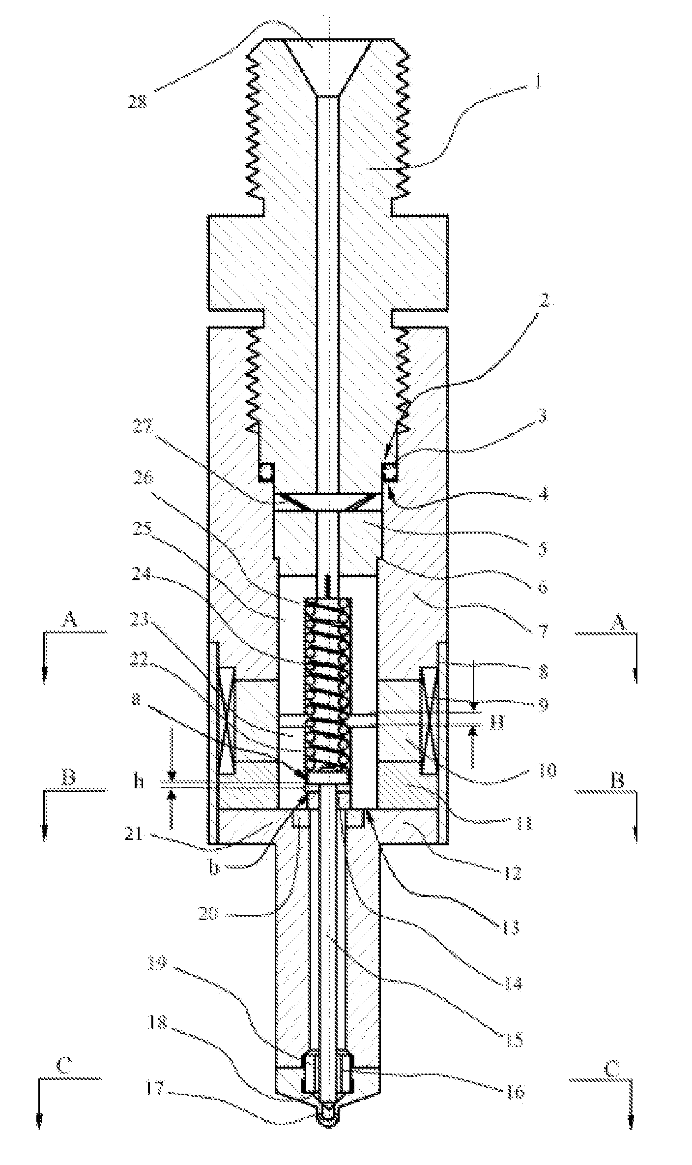
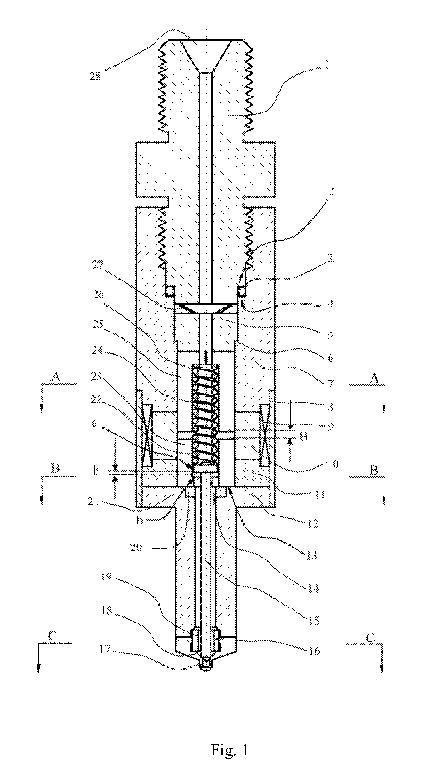
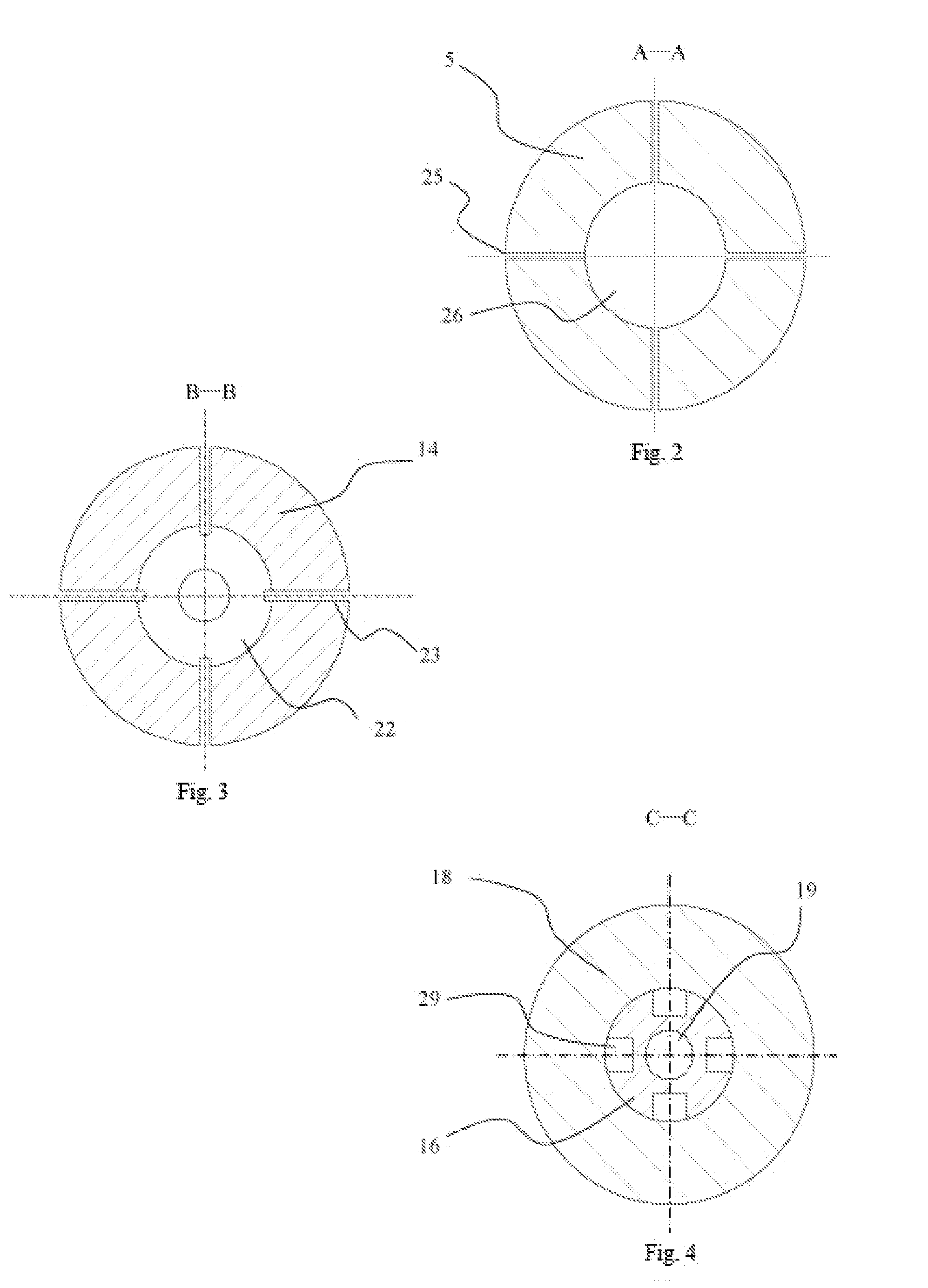
[0030]Referring to FIG. 1, the common rail electronic control injector comprises: a fuel inlet joint 1, a fuel inlet 28 located at an outer end of the fuel inlet joint 1, an electromagnet device, a nozzle body 12, a needle valve 15, a valve seat 18 and spray holes 17. The electromagnet device comprises a static core 5, an armature 14, wherein a working gap “H” is formed therebetween, and a coil 9.

[0031]The armature 14 is moveably connected with the needle valve 15 along an axial direction. A distance “h” is between the armature 14 and the needle valve 15 along the axial direction at a power-off reset state of the electromagnet device. After the electromagnet device is power-on, the armature 14 firstly closes to the needle valve 15, secondly impacts the needle valve 15, and moves towards the static core 5 together with the needle valve 15 a...


PUM


Abstract

The present invention relates to a common rail electronic control injector, which belongs to the electronic control fuel injection system technology. The injector includes an oil inlet joint, an oil inlet located at outside the oil inlet joint, an electromagnet device, a nozzle body, a needle valve, a valve seat and spray holes, wherein the electromagnet device includes a static core, an armature and a coil, wherein a working gap between the static core and the armature is H, the armature is moveably connected with the needle valve along an axial direction. The present invention further includes a compression spring applying a force to the needle valve, a force mechanism applying a force to the armature, and a block mechanism providing an axial anti-thrust while the armature is reset. The present invention has advantages of lower manufacturing cost, better reliability and smaller driving energy.

Description

BACKGROUND OF THE PRESENT INVENTION[0001]1. Field of Invention[0002]The present invention relates to a common rail electronic control injector, and more particularly to a common rail electronic control injector for a common rail type electronic control fuel injection system of a compression ignition engine (diesel).[0003]2. Description of Related Arts[0004]The function of the common rail electronic control injector is to control the injection's start and end of the injector by using electrical pulse signals. The existing technology, such as the common rail electronic control injectors for the CR system of BOSCH Corporation, the ECD-U2 system of Japan's DENSO Corporation, the UNIJET system of Italian FIAT Group, the LDCR system of British DELPHI DIESEL SYSTEMS Corporation, has common characteristics that it comprises a solenoid valve and a control room controlled by the solenoid valve, the electromagnetic force firstly controls a switch action of the solenoid valve for changing the p...

Claims


Application Information

Patent Timeline
IPC IPC(8): F02M69/46F02M51/00
CPCF02M51/0671F02M51/0685F02M2200/9038F02M2200/08F02M2200/02
Inventor WANG, YANGZHANG, XIAOZHU, TAOXU, SHUAIQINGXIONG, QIANYAO, MINGFATIAN, QINGYUNHE, FANGZHANG, ZHONG
Owner TIANJIN UNIV
Why Eureka
Try Eureka