Rotating electric machine and drive device

a technology of rotating electric machines and drive devices, which is applied in the direction of electric devices, magnetic circuit rotating parts, magnetic circuit shapes/forms/construction, etc., can solve the problems of poor temperature characteristics, irreversible demagnetization of magnets, and deterioration of the performance of rotating electric machines, so as to reduce the variation of cooling performance of coolant, prevent thermal demagnetization of magnets, and efficiently cool permanent magnets

Inactive Publication Date: 2010-09-23
TOYOTA JIDOSHA KK
View PDF11 Cites 32 Cited by
  • Summary
  • Abstract
  • Description
  • Claims
  • Application Information

AI Technical Summary

Benefits of technology

[0013]In the rotating electric machine according to the present invention, the partition wall and the path wall are formed inside the second coolant channel. In the second coolant channel, therefore, the coolant flows toward the outer peripheral edge region of the axial end surface of the core body where the permanent magnet is placed. Thus, it is possible to efficiently cool the permanent magnet in such a manner that the coolant which is low in temperature is constantly supplied to the permanent magnet. Moreover, the coolant flow at the axial end surface of the core body forming the second coolant channel is prescribed in one direction which is opposite to the rotation direction. Therefore, the coolant is prevented from being retained at the axial end surface. As a result, it is possible to constantly supply the coolant throughout the axial end surface in the circumferential direction. Thus, it is possible to suppress the variation of cooling performance of the coolant that cools the permanent magnet (cooling variations). Further, it is possible to prevent thermal demagnetization of the magnet.

Problems solved by technology

Such an Nd magnet is excellent in magnetic characteristic, but is poor in temperature characteristic because holding power becomes deteriorated as temperature increases (thermal demagnetization).
In the Nd magnet, the deterioration of the holding power causes such a problem that the magnet is demagnetized in an irreversible manner because of an external anti-magnetic field.
This problem results in deterioration of performance of the rotating electric machine.

Method used


Image

  • Rotating electric machine and drive device
  • Rotating electric machine and drive device
  • Rotating electric machine and drive device

Examples


embodiment 1

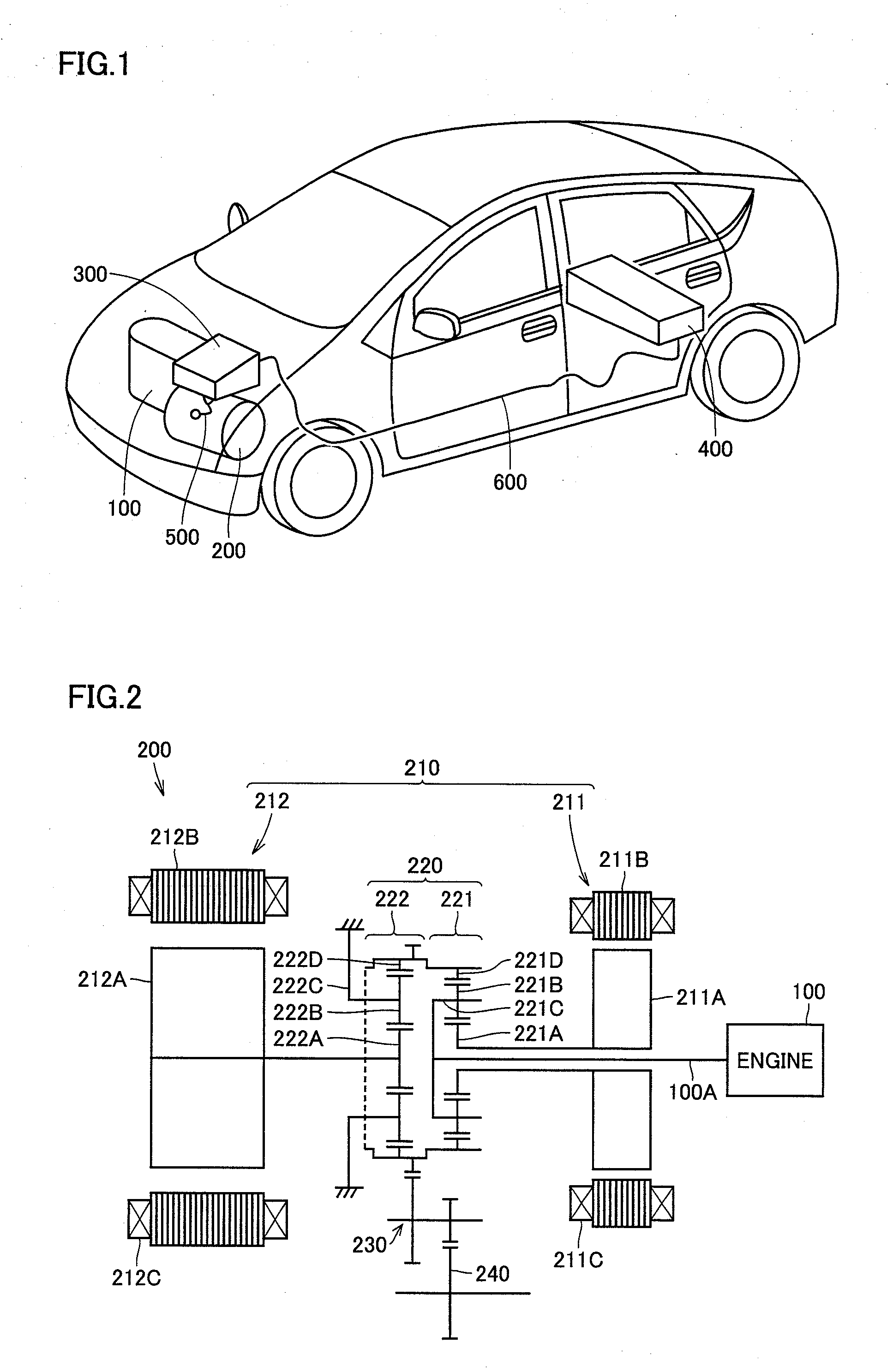
[0022]FIG. 1 is a general drawing that shows a configuration of a hybrid vehicle according to Embodiment 1 to which a rotating electric machine is applied. As shown in FIG. 1, the hybrid vehicle according to this embodiment includes an engine 100, a drive unit 200, a PCU 300 and a battery 400. Drive unit 200 is electrically connected to PCU 300 by way of a cable 500. Moreover, PCU 300 is electrically connected to battery 400 by way of a cable 600.

[0023]Engine 100, which is an internal combustion engine, may be a gasoline engine or a diesel engine. Drive unit 200 generates a driving force for driving the vehicle, in cooperation with engine 100. Both engine 100 and drive unit 200 are installed in an engine room of the hybrid vehicle. PCU 300 is a control device that controls operations of drive unit 200. Battery 400 is a chargeable / dischargeable secondary battery. The hybrid vehicle is driven by engine 100 and drive unit 200 to which battery 400 feeds electric power, and each of engin...

embodiment 2

[0063]The rotating electric machine, which is described in Embodiment 1 and has the partition wall and the path wall each formed therein, is preferably used as a rotating electric machine which is rotatable in only one direction, such as a prime motor to be directly coupled to an axle. In some instances, on the other hand, the rotating electric machine according to Embodiment 1 in which the coolant flow is prescribed in one direction is not suitable for a rotating electric machine which is rotatable in two directions such that a frequency of rotation in one direction is equal to a frequency of rotation in the other direction, such as a motor which also serves as a speed reducer. For this reason, the coolant flow is changed in response to the rotation in the two directions. Thus, it is possible to provide a cooling structure suitable for the rotating electric machine which is rotatable in the two directions.

[0064]FIG. 6 is a partially sectional schematic drawing that shows a modifica...


PUM


Abstract

There is provided a rotating electric machine capable of preventing a coolant from being retained at an outer surface of a rotor. This rotating electric machine includes a rotation shaft provided so as to be rotatable, a core body secured to the rotation shaft, a permanent magnet embedded in the core body, and an end plate provided so as to be opposed to an axial end surface of the core body. A first coolant channel is formed in the rotation shaft to allow a coolant to flow therethrough. A second coolant channel is formed between the end plate and the axial end surface of the core body to communicate with the first coolant channel. A partition wall that partitions the second coolant channel in a circumferential direction and a path wall that guides the coolant in the second coolant channel toward an outer peripheral edge region of the axial end surface where the permanent magnet is placed are formed inside the second coolant channel.

Description

TECHNICAL FIELD[0001]The present invention relates to a rotating electric machine and a drive device. In particular, the present invention relates to a rotating electric machine having a permanent magnet embedded therein, and a drive device including the rotating electric machine.BACKGROUND ART[0002]In a rotating electric machine having a permanent magnet embedded therein, a rare-earth magnet is occasionally used as the permanent magnet in order to realize high efficiency and size reduction. In particular, an Nd (neodymium) magnet having a considerably high magnetic characteristic is used occasionally. Such an Nd magnet is excellent in magnetic characteristic, but is poor in temperature characteristic because holding power becomes deteriorated as temperature increases (thermal demagnetization). In the Nd magnet, the deterioration of the holding power causes such a problem that the magnet is demagnetized in an irreversible manner because of an external anti-magnetic field. This probl...

Claims


Application Information

Patent Timeline
Patent Type & Authority Applications(United States)
IPC IPC(8): H02K1/32
CPCH02K1/276H02K9/08H02K9/06H02K1/32B60L3/0061B60L7/14B60L15/2009B60L15/2054B60L2210/10B60L2210/40B60L2220/52B60L2240/36B60L2240/423B60L2240/425B60L50/16B60L50/61B60L50/66Y02T10/62Y02T10/64Y02T10/70Y02T10/7072Y02T10/72Y02T90/16
Inventor TATEMATSU, KAZUTAKATAKETSUNA, YASUJITANAHASHI, FUMIKIARAKAWA, ATOMI
Owner TOYOTA JIDOSHA KK
Why Eureka
Try Eureka