Metallic porous body incorporated by casting into a heat exchanger

a heat exchanger and porous body technology, applied in the direction of water-tube boilers, steam boiler components, water-tube boilers, etc., can solve the problems of high scrap and waste, inability to use such a heat exchanger element on its own in the boiler, and insufficient effective quality of these bonds, etc., to achieve low weight and high output

Inactive Publication Date: 2010-09-30
BEKAERT COMBUSTION TECH
View PDF3 Cites 19 Cited by
  • Summary
  • Abstract
  • Description
  • Claims
  • Application Information

AI Technical Summary

Benefits of technology

[0010]An aspect of the claimed invention provides a heat exchanger element intended for a central heating boiler having a higher output than the known central heating boilers with comparable dimensions, the intended heat exchanger element being particularly compact and having low weight.
[0012]The heat exchanger element has a very flat design, wherein the flue gas draft is wide but not deep (as can be seen in FIG. 1A), which is possible due to the use of shorter and smaller pins and / or fins as heat exchange surface enlarging structures, compared to the ones used in conventional heat exchanger elements for boilers. The use of these pins and / or fins, with their great surface-content ratio and heat exchanging action, makes it possible to cool down the flue gas and to transfer the heat efficiently to the water-cooled walls. The cooling of the long walls in the heat exchanger element is established by a parallel path in a one-piece water channel. This one-piece water channel core renders the manufacture of the core and the positioning of the core in a sand-casting mold relatively simple, so that the manufacture of the heat exchanger element is relatively simple as well and, accordingly, can take place in an economically favourable manner. As is evident for a person skilled in the art, the water-channel core can be built of different pieces put together to form the water-channel core.
[0014]Surprisingly, it was found that the porous metallic body was not affected by the hot molten metal, cast onto the porous metallic body and that a good metallic bond was obtained between the porous metallic body and the cast heat exchanger element. And also that the aluminium-oxides present at the surface of the porous aluminium material did not inhibit a good connection between the porous material and the heat exchanger element. The struts or ligaments of the metallic porous body stay intact into the complete co-cast structure and are properly surrounded by the melt (see FIG. 4) creating a big contact surface, which results in a very good heat transfer and is—by the turbulence enhancing 3-D structure of the porous material—able to extract even more heat from the flue gasses, enhancing further the efficiency of the heat exchanger element.
[0016]The heat exchanger element is manufactured as a co-casting, comprising the steps of claim 5, 6 or 7, and can be manufactured in a relatively quick and efficient manner.

Problems solved by technology

The use of such a heat exchanger element on its own in a boiler is not possible as the metallic foam would melt by the heat of the flue gases.
On the other hand, casting of complex structures together with the already complex open cell foam body (as an example of a metallic porous structure) is a rather difficult job, resulting in a lot of scrap and waste.
But the effective quality of these bonds is not always satisfactory.
One can achieve a proper mechanical bond between a porous aluminium body and a solid metal carrier, by, for example soldering, but as this method uses an extra material, heat dissipation from carrier to porous structure, or the other way around can be distorted and the extra material, e.g. Zn, can give corrosion problems at the bonding place and even have the effect of a thermal insulating layer.
It also gives an end product which is limited in use for heat applications, i.e. limited by the melting temperature of Zn in the solder.
When these aluminium-oxides are not sufficiently removed, no good heat conduction bond can be obtained.

Method used


Image

  • Metallic porous body incorporated by casting into a heat exchanger
  • Metallic porous body incorporated by casting into a heat exchanger
  • Metallic porous body incorporated by casting into a heat exchanger

Examples


Embodiment Construction

[0054]The present invention will be described with respect to particular embodiments and with reference to certain drawings but the invention is not limited thereto but only by the claims. The drawings described are only schematic and are non-limiting. In the drawings, the size of some of the elements may be exaggerated and not drawn on scale for illustrative purposes. The dimensions and the relative dimensions do not necessarily correspond to actual reductions to practice of the invention.

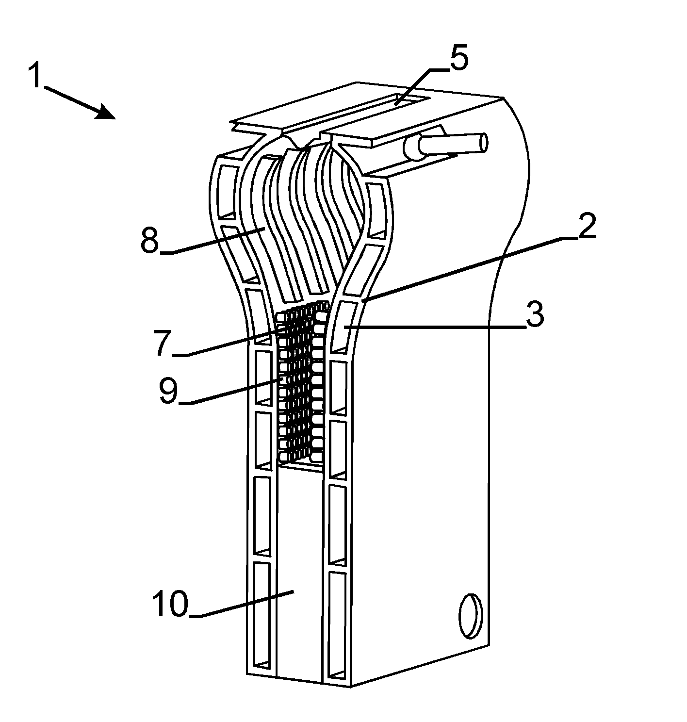
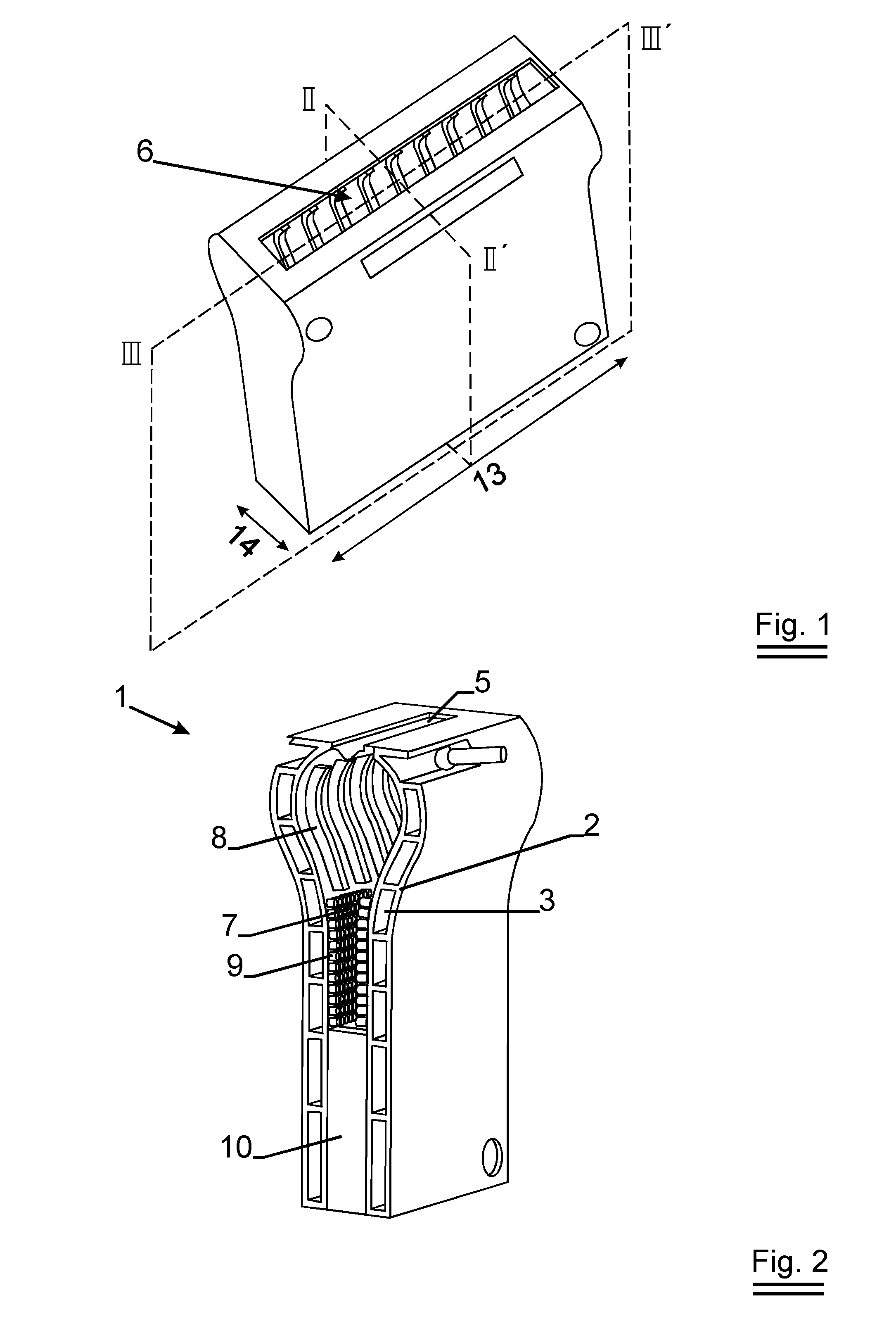
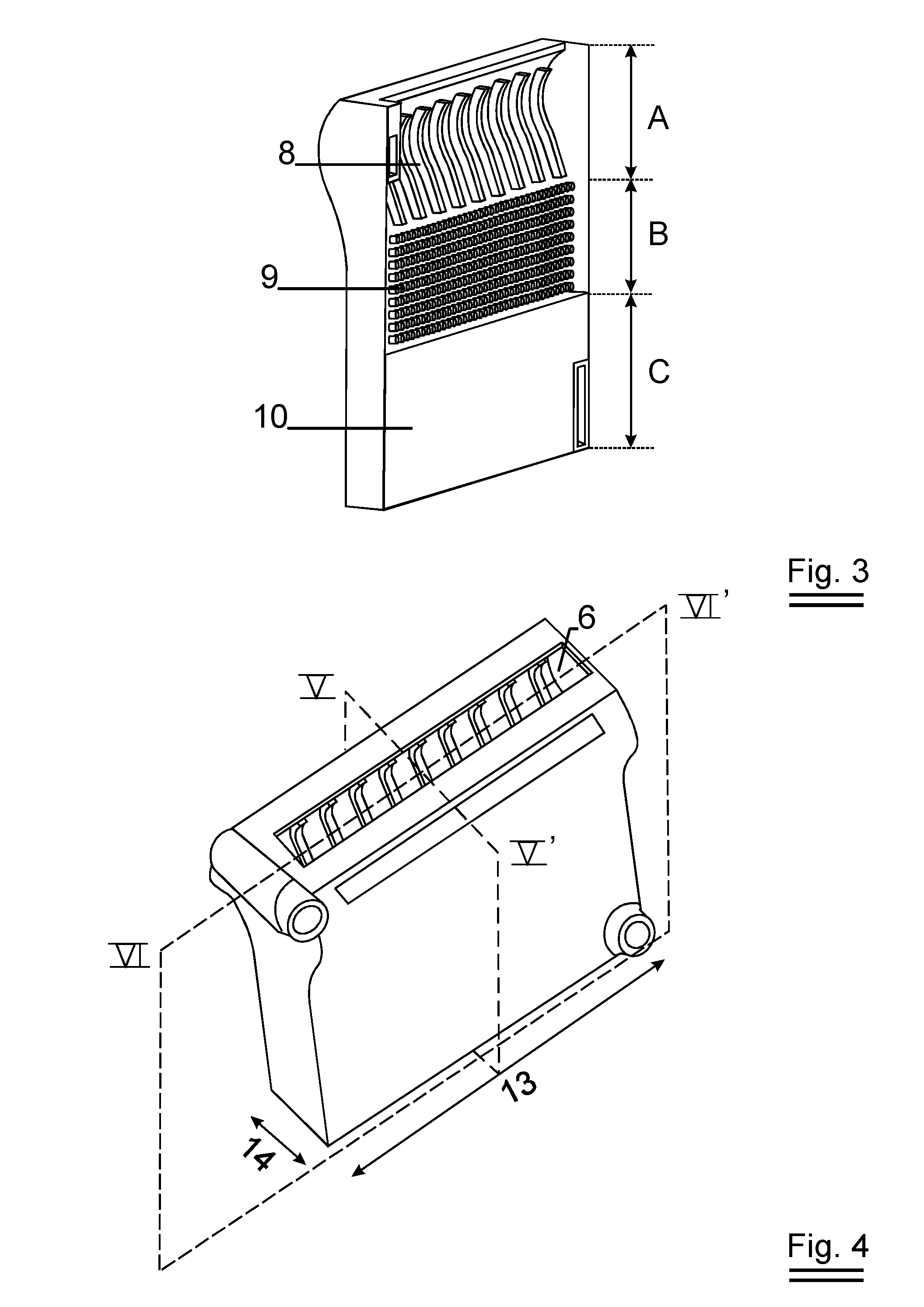
[0055]FIGS. 1, 2 and 3 show an exemplary embodiment of the heat exchanger 1 according to the invention. Heat exchanger 1 is manufactured as a co-casting substantially from aluminium. The heat exchanger comprises a number of walls 2, which walls enclose on one side a water carrying channel 3 and on the other side a flue gas draft 7. The flue gas draft 7 extends from the burner space 6. The burner space 6 is intended for accommodating a burner. Preferably, the burner is a metal fiber burner membrane...


PUM

PropertyMeasurementUnit
lengthaaaaaaaaaa
porosityaaaaaaaaaa
porosityaaaaaaaaaa

Abstract

The present invention relates to a co-cast heat exchanger element intended for a central heating boiler, which heat exchanger element is made from substantially aluminum, the heat exchanger element being provided with walls which enclose a water carrying channel, and with at least one wall which encloses at least one flue gas draft to which a burner can be connected, at least one wall which encloses the at least one flue gas draft being water-cooled in that it also forms a boundary of the water-carrying channel, while one of the water-cooled walls is provided with heat exchanging surface enlarging pins and / or fins which extend in the respective flue gas draft and is also provided with other heat exchanging surface enlarging metallic porous structures.

Description

TECHNICAL FIELD[0001]The present invention relates to a co-cast heat exchanger element intended for a central heating boiler, which heat exchanger element is made from substantially aluminum, the heat exchanger element being provided with walls which enclose a water carrying channel, and with at least one wall which encloses at least one flue gas draft to which a burner can be connected, at least one wall which encloses the at least one flue gas draft being water-cooled in that it also forms a boundary of the water-carrying channel, while at least one of the water-cooled walls is provided with heat exchanging surface enlarging pins and / or fins which extend in the respective flue gas draft and is also provided with other heat exchange surface enlarging metallic porous structures.[0002]The present invention also relates to a method for obtaining such a co-cast heat exchanger element and its use in a central heating boiler.BACKGROUND ART[0003]A heat exchanger according to above describ...

Claims


Application Information

Patent Timeline
Patent Type & Authority Applications(United States)
IPC IPC(8): F22B37/00F28F3/12B21D53/02F28F7/00
CPCB22D19/0063F24H1/26F24H1/38F24H9/0026F28F3/048Y10T29/4935F28F13/003F28F21/08F28F2255/14F28F3/022F28F3/12
Inventor HUBAU, KARELBEUKERS, JOHANNESTHIJSSEN, PAULVAN PETEGHEM, JANGEELEN, FRANK
Owner BEKAERT COMBUSTION TECH
Why Eureka
Try Eureka