High-powered laser beam welding and assembly therefor

a high-power laser and laser beam technology, applied in welding/soldering/cutting articles, metal working devices, manufacturing tools, etc., can solve the problems of large amount of weld spatter and weld metal discontinuities, and the general limitation of welding with high-power lasers to relatively thin metal thicknesses

Inactive Publication Date: 2010-09-30
GENERAL ELECTRIC CO
View PDF7 Cites 28 Cited by
  • Summary
  • Abstract
  • Description
  • Claims
  • Application Information

AI Technical Summary

Benefits of technology

[0008]The present invention generally provides a method for welding metallic materials using a high-powered laser beam, by which the weld keyhole is stabilized and the incidence of spattering and weldment discontinuities is reduced. The method is particularly well suited for welding components formed of nickel-based, iron-based alloys, cobalt-based, copper-based, aluminum-based, and titanium-based alloys, nonlimiting examples of which include alloys used in the fabrication of gas turbine components.
[0011]As a result of the ability to stabilize a high-powered laser beam for welding applications and reduce spattering and weldment discontinuities, potential advantages of the invention include the ability to join greater material thicknesses using laser technology. In so doing, advantages of high-powered laser beam welding become available for a variety of products, including but not limited to power generation, aerospace, infrastructure, medical, and industrial applications.

Problems solved by technology

Although some stabilization of the weld keyhole can be achieved with this approach, a significant amount of weld spatter and weld metal discontinuities still result.
In view of the above, welding with high-powered lasers has been generally limited to relatively thin metal thicknesses (less than 1 cm, more typically less than 2.5 mm) due to weld pool instability.

Method used


Image

  • High-powered laser beam welding and assembly therefor
  • High-powered laser beam welding and assembly therefor
  • High-powered laser beam welding and assembly therefor

Examples


Embodiment Construction

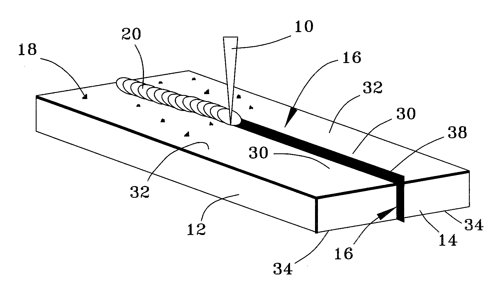
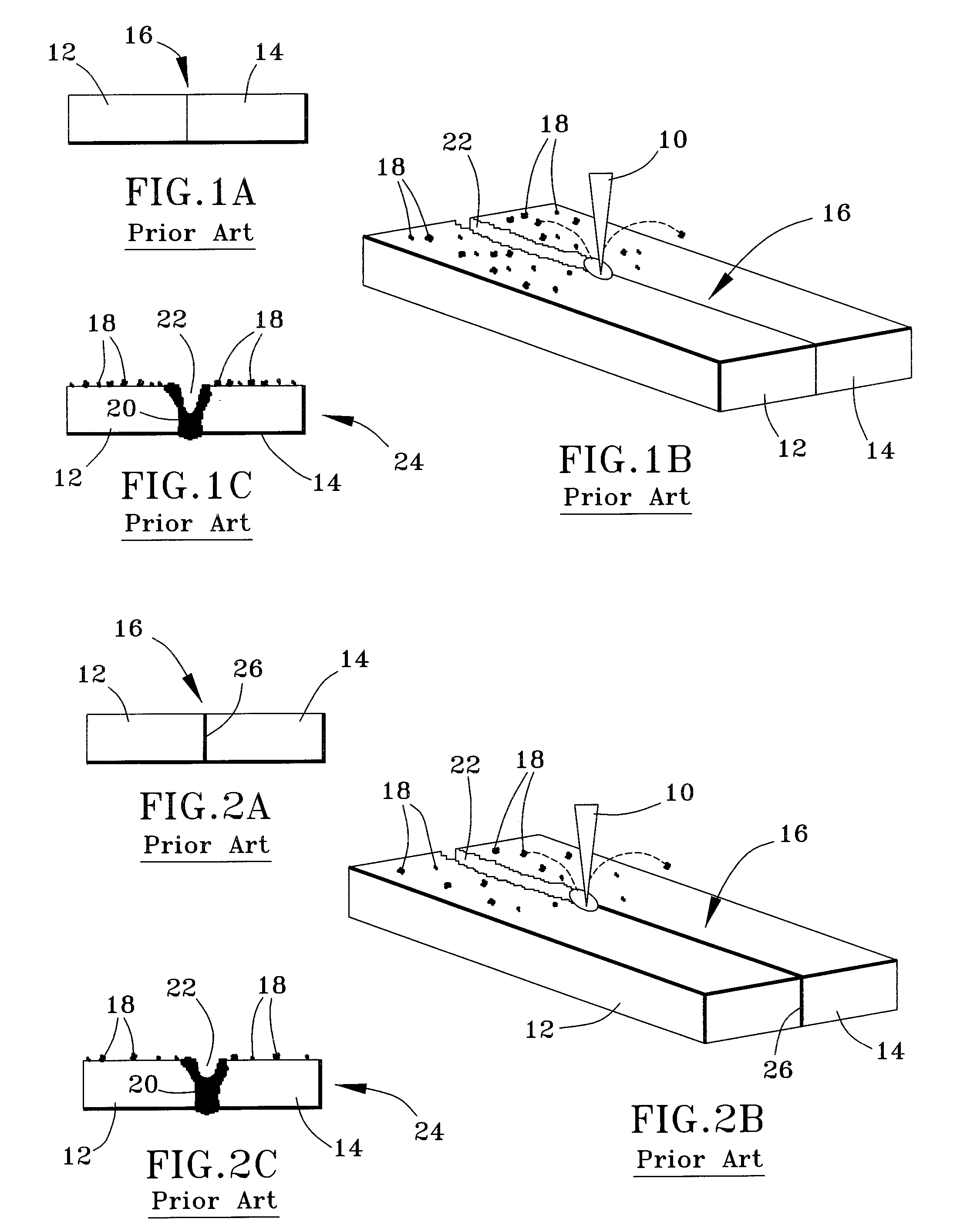
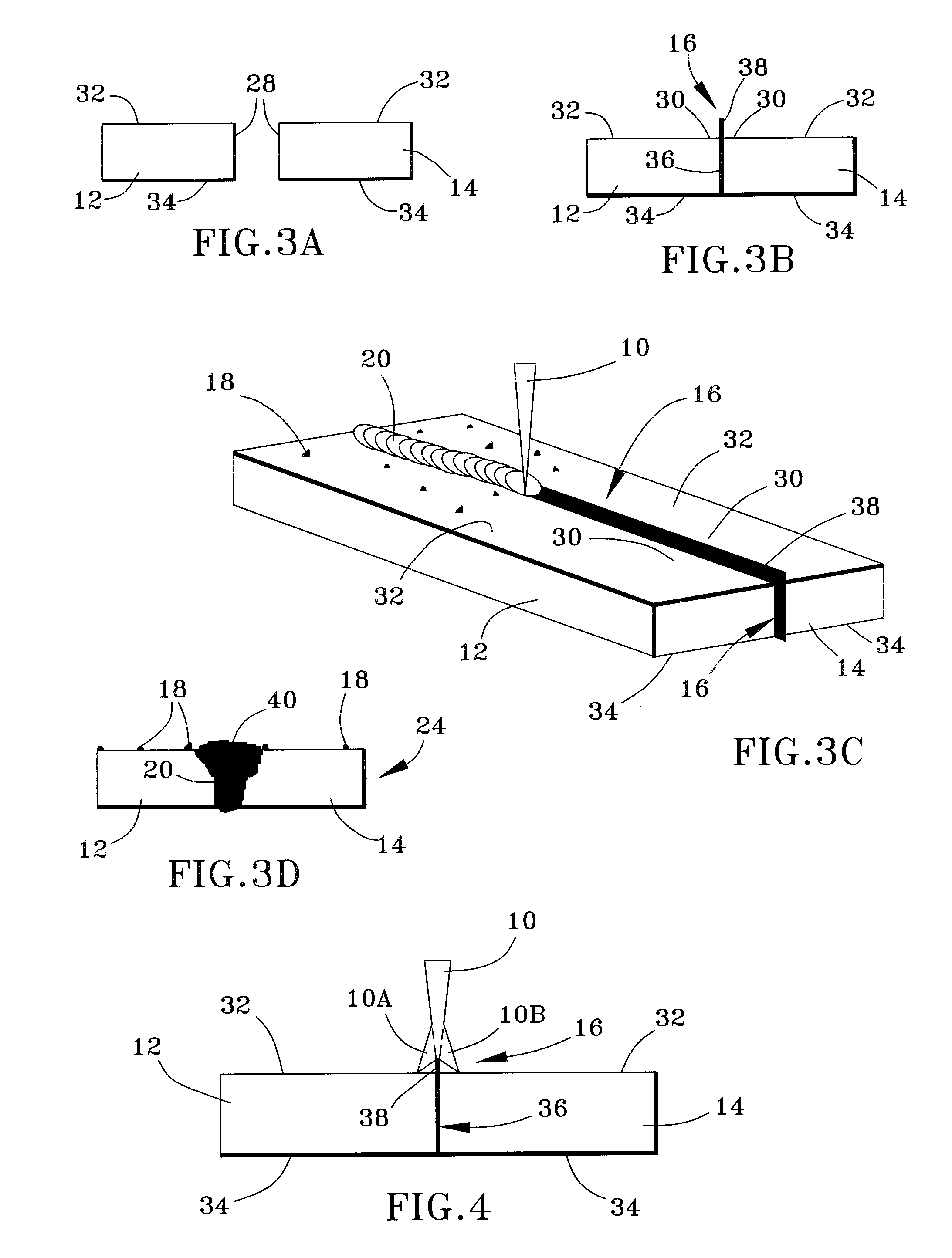
[0017]FIGS. 3A through 3D and 4 represent a process for high-powered laser beam welding articles to create a weld joint 20 (FIGS. 3C and 3D) that extends entirely through the thickness of the articles without creating discontinuities and with minimal spattering during the welding process. The process is particularly well suited for fabricating components for gas turbines used in power generation and aerospace applications, though the process can be utilized to produce components for a wide variety of applications, including infrastructure, medical, industrial applications, etc. For convenience, reference numbers used in prior art FIGS. 1A-1C and 2A-C are also used in FIGS. 3A-D and 4 to identify functionally similar elements.

[0018]FIG. 3A represents a pair of articles 12 and 14 that can be welding using a high-powered laser beam welding process of this invention. The articles 12 and 14 may be castings, wrought, or powder metallurgical form, and may be formed of a variety of material...


PUM

PropertyMeasurementUnit
power levelaaaaaaaaaa
diameteraaaaaaaaaa

Abstract

A welding method and an assembly for performing the method. Articles to be welded are placed together so that faying surfaces thereof face each other, a joint region is defined by the faying surfaces and juxtaposed surfaces of the articles, a shim is between and contacts the faying surfaces, and an edge portion of the shim protrudes from the juxtaposed surfaces. The articles are welded together by projecting onto the joint region a high-powered laser beam that is focused on the juxtaposed surfaces and intentionally unfocused on the edge portion of the shim so that portions of the laser beam are diffracted by the edge portion onto the juxtaposed surfaces. The laser beam and its diffracted portions melt the shim and the faying and juxtaposed surfaces of the articles. Cooling of the articles yields a welded assembly having a weld joint entirely through a through-thickness of the welded assembly.

Description

BACKGROUND OF THE INVENTION[0001]The present invention generally relates to welding methods. More particularly, this invention is directed to a method for welding metallic materials using a high-powered laser beam, by which the weld keyhole is stabilized to reduce spattering and weldment discontinuities.[0002]Various metallic alloys, including nickel-, iron-, and cobalt-based superalloys, are widely used to form components of gas turbine engines. Metallic components are often formed by casting, and for some applications are preferably or necessarily fabricated by welding or brazing as a result of complex geometries or other assembly considerations.[0003]Low-heat input welding processes, and particularly high-energy beam welding processes such as laser beam and electron beam welding (LBW and EBW, respectively) operated over a narrow range of welding conditions, have been successfully used to produce crack-free weld joints in single-crystal and polycrystalline superalloys and other me...

Claims


Application Information

Patent Timeline
Patent Type & Authority Applications(United States)
IPC IPC(8): B23K26/20
CPCB23K26/203B23K2203/08B23K2201/18B23K26/26B23K26/211B23K2101/18B23K2103/02B23K2103/08B23K2103/10B23K2103/12B23K2103/14B23K2103/26
Inventor NOWAK, DANIEL ANTHONY
Owner GENERAL ELECTRIC CO
Why Eureka
Try Eureka