Mass spectrometer

a mass spectrometer and mass spectrometer technology, applied in the field of timeofflight mass spectrometer, can solve the problems of difficult to secure the orthogonality between the ion track and the incident surface of the mcp, affect the detection accuracy of the time of flight, etc., and achieve the effect of easy replacement of the mcp, easy to secure the orthogonality, and easy to ensure the accuracy of the mcp

Inactive Publication Date: 2010-09-30
HAMAMATSU PHOTONICS KK
View PDF4 Cites 23 Cited by
  • Summary
  • Abstract
  • Description
  • Claims
  • Application Information

AI Technical Summary

Benefits of technology

[0012]In the mass spectrometer according to the present invention, because the MCP having an ion incident surface is directly fixed to a vacuum vessel body by the input-side electrode, it is easy to secure orthogonality between the ion incident surface and an ion track, and replacement of the MCP i

Problems solved by technology

This is because, if the ion incident surface has an inclination, the length of a flight track differs depending on the position of the ion incident surface, which affects the detection accuracy of a time of flight.
Because an incident surface of

Method used


Image

  • Mass spectrometer
  • Mass spectrometer
  • Mass spectrometer

Examples


first embodiment

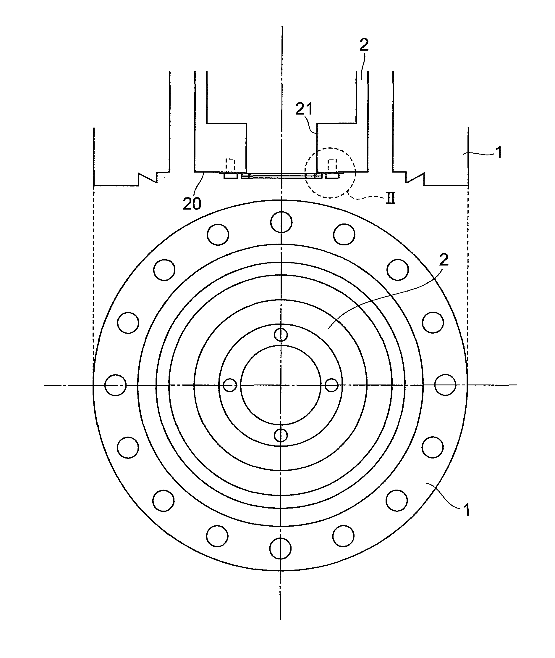
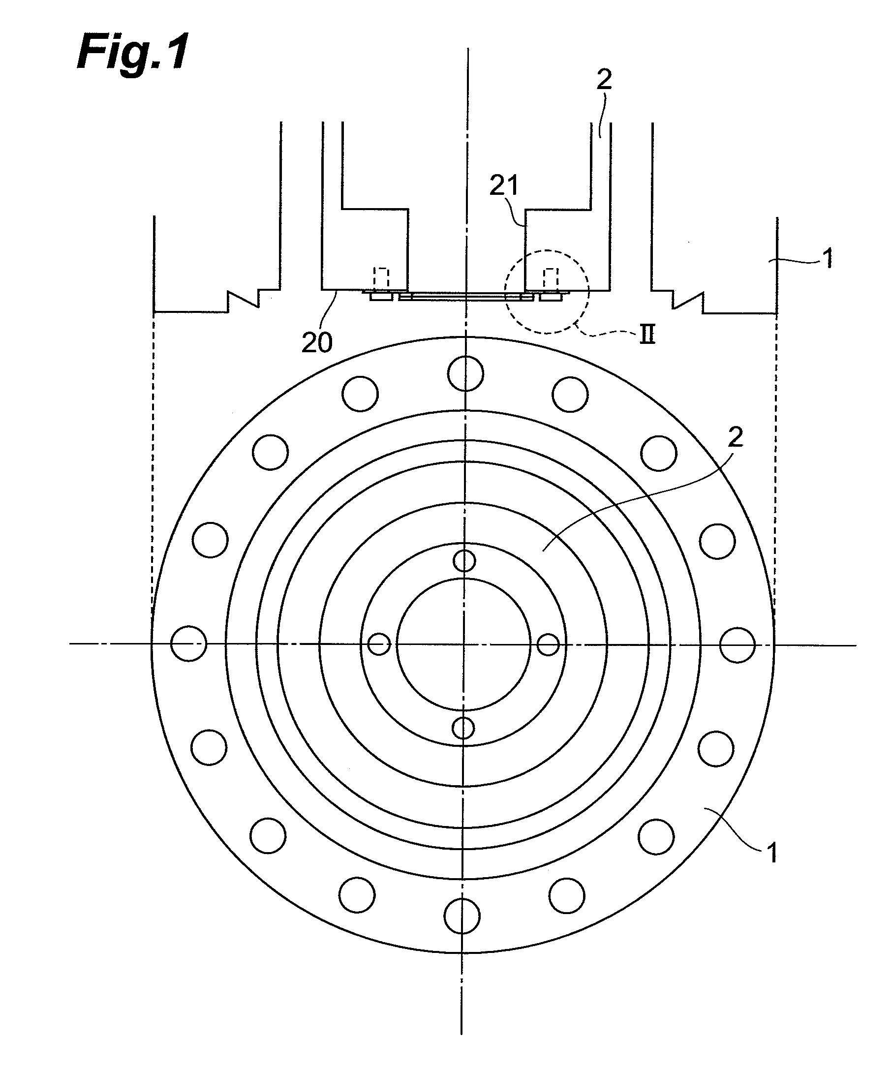
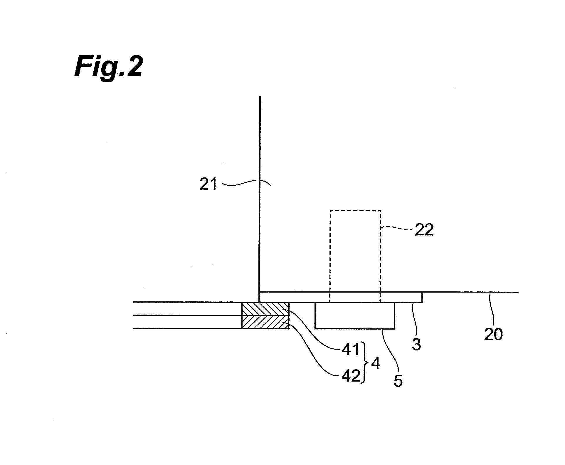
[0030]FIG. 1 is a view showing a structure of a flight tube end portion in a mass spectrometer according to the present invention, FIG. 2 is an enlarged view of a II part thereof, FIG. 3 is a view showing a structure of a vacuum flange, FIG. 4 is an enlarged view of a IV part thereof, FIG. 5 are views showing a structure of a circuit board, FIG. 6 shows an equivalent circuit thereof, and FIG. 7 shows an assembled state.

[0031]The flight tube 2 is a cylindrical structure to be arranged in a body 1 of the mass spectrometer. At its end portion of a side that has not been illustrated, an ion source is arranged. On the other hand, at the illustrated end portion, two disk-like MCPs 41 and 42 (hereinafter, collectively referred to as an MCP group 4) are arranged. The MCPs 41 and 42 are bonded to each other by a conductive thermoplastic adhesive, and further, an MCP-IN electrode 3 formed of an annular metal is bonded to an MCP 41-side surface by the same conductive thermoplastic adhesive. Th...

second embodiment

[0040]In the second embodiment shown in FIG. 8 and FIG. 9, an insulator 52 being a circular cylindrical insulator is arranged on a through-hole for a screw provided in the MCP-IN electrode 3, a hooked clamp 51 is thereon arranged, and by fixing the clamp 51, the insulator 52, and the MCP-IN electrode 3 with a screw 50 screwed in a screw hole of the flight tube 2, the MCP group 4 is fixed. The screw 50 is an insulating screw formed of a PEEK (polyetheretherketone) resin or a Teflon resin, and the clamp 51 and the MCP group 4 are separated in potential from each other.

third embodiment

[0041]In the third embodiment shown in FIG. 10 and FIG. 11, the MCP-IN electrode 3 is fixedly fitted at an end portion of the flight tube 2 by bonding, welding, or the like, and thereon attached via an arc-shaped insulator 54 is a fixing plate 53 formed of a metal plate which is likewise in an arc shape, by an adhesive or the like. The MCP group 4 is arranged inserted in a groove part formed between the fixing plate 53 and the MCP-IN electrode 3. In this case as well, the fixing plate 53 and the MCP group 4 are separated in potential from each other.

[0042]It becomes possible also in these second and third embodiments as in the first embodiment to secure orthogonality of the incident surface of the MCP group 4 with respect to the ion flight track in the flight tube 2 at high accuracy. Moreover, in these embodiments, there is also an advantage that only the MCP group 4 can be easily replaced.

[0043]The configuration of the detector side is also not limited to that shown in the first em...


PUM


Abstract

A mass spectrometer that allows easy replacement of an MCP (microchannel plate) and is enabled to secure orthogonality between an incident surface of the MCP and an ion track at high accuracy is provided. A flight tube 2 where ions fly is arranged in a vacuum vessel composed of a vacuum flange 6 and a body 1, and an MCP group 4 is attached to a tail end of the flight tube 2 via an MCP-IN electrode 3. A vacuum flange 6 is attachably and detachably attached to the body 1, and the MCP group 4, by a spring 710 provided on a circuit board 7 for detection attached to the vacuum flange 6, is urged toward an end portion of the flight tube 2 so that its orthogonality with respect to an ion flight track is secured.

Description

BACKGROUND OF THE INVENTION[0001]1. Field of the Invention[0002]The present invention relates to a time-of-flight mass spectrometer (TOF-MS) used for detection of the molecular weight of a polymer and the like.[0003]2. Related Background Art[0004]In a TOF-MS, the mass of detecting ions is detected based on time required for the detecting ions to fly within a vacuum flight tube. An apparatus of a type disclosed in JP2007-87885A has been known as a charged-particle detecting apparatus to be used as a detector in such a TOF-MS.[0005]This charged-particle detecting apparatus has a detecting section including a microchannel plate (MCP) arranged on a vacuum flange, and thus has a configuration that makes it easy to replace the MCP when the detector reaches its life end.SUMMARY OF THE INVENTION[0006]Meanwhile, in the TOF-MS, a mass detection accuracy of detecting ions depends on a detection accuracy of a time of flight, that is, a half-value width of an output signal to be output when the ...

Claims


Application Information

Patent Timeline
IPC IPC(8): H01J49/40H01J49/24H01J49/08
CPCH01J49/40H01J49/025
Inventor SUYAMA, MOTOHIROIIZUKA, ETSUOSUZUKI, AKIOKOBAYASHI, HIROSHI
Owner HAMAMATSU PHOTONICS KK
Why Eureka
Try Eureka